INS aligment
-
You can only use external help via GPS to keep it in line.
Nope, if GPS never fails, INS positioning would be extinct. On GPS drops out, it’s the pilots tasked to do manual position correction using a landmark with known Lad/Long coors and GM radar or “fly over”. Or, TACAN/TCN (?) can be used. Or, before GPS was invented, radio stations where used to DF “direction find”.
INS Attitude does not need drift correction or it could be said the code self corrects.
For INS heading (rate gyro suite) non-GPS drift correction, I have no idea what the F-16 procedure is.
My order of probability for non-GPS INS heading drift correction is:
Fluxgate compass (automatic, maybe) If there is HUD heading without GPS or ground allignment, it must have one.
Pilot’s backup compass (pilot manual input) geeeee I can’t believe I posted that
North Star (pilot manual input)
Gyrocompass (?) It maybe the primary with the others being backups and/or check sums. I listed it last because I don’t know drift spec or anything about this type of device. Never used it.For non-GPS altitude drift correction, altimeter could be used. This may not be F-16 applicable.
-
GPS is good(ish) for position but for attitudes and accelerations not so much. Flight information, FLCS and fire control would be crippled to put it mildly. Of course an aircraft designed without an INS wouldn’t be designed to be dependent on an INS

I’ve heard of self-correcting INSs having problems assuming long durations of constant attitude/accel was straight and level on some more ancient craft.
I’m positive that either the baro or radio altimeter can be used to update flight altitude “ACAL” in the F-16
As far as I know in-flight alignment doesn’t attempt position or gyrocompassing and it just sets the attitude with the heading set manually by the little knob on the center console near the HSI.
-
As far as I know in-flight alignment doesn’t attempt position or gyrocompassing and it just sets the attitude with the heading set manually by the little knob on the center console near the HSI.
I think the same. Will ask F-16 driver’s confirmation …
-
GPS is good(ish) for position but for attitudes and accelerations not so much. Flight information, FLCS and fire control would be crippled to put it mildly. Of course an aircraft designed without an INS wouldn’t be designed to be dependent on an INS
The FLCS doesn’t care if your entire INS/GPS is down. It will work just fine. The only thing it requires from external sources are pitot and static pressure inputs to adjust flight control scheduling. It gets those from the air data system, not the INS or GPS.
As far as I know in-flight alignment doesn’t attempt position or gyrocompassing and it just sets the attitude with the heading set manually by the little knob on the center console near the HSI.
The IFA mode you are referring to is just the attitude mode. Either an auto or manual IFA will give you more data than just attitude mode. However even the CDCs point to manual IFA or attitude mode is only good for getting your butt home. I’m not sure how much an auto IFA will drift or if GPS can keep that in line. Auto IFA is achieved with GPS data as well as some specific pilot inputs. All 3 modes require input from the pilot of the magnetic heading and the accuracy of any of those alignments is directly affected by how good the pilot is at entering that data accurately and following the cues to perform certain turns during the process.
-
I hope it have. (not necessarily a compass … but a flux-gate … I’m almost sure! There is no reason not to have one for crosscheck of computed mag heading and as a backup for IRS heading.)
Nope, the only compass in the aircraft is the backup compass you see on the right console. It is just a standard two bar magnet compass, nothing special about it.
-
GPS is good(ish) for position but for attitudes and accelerations not so much. Flight information, FLCS and fire control would be crippled to put it mildly. Of course an aircraft designed without an INS wouldn’t be designed to be dependent on an INS
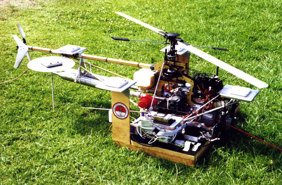
Single antenna GPS does not do attitude. I know a multi antenna GPS system will and also does heading, using differential carrier wave phase mode(needs base station GPS). This is an Autonomous Helicopter with four antennas. Their 1995 system did not have INS. This is a newer system.
As for acceleration, GPS computes a velocity vector (GS and direction) by
new position - old position /time (ABS). Little more math it could do acceleration. It would be laggy compared to an accelerometer.I don’t see a single antenna GPS computing heading either. Heading is where the nose is pointing. Velocity vector is the FPM. If the a/c is crabbing these two vectors are not the same. Single antenna GPS has no idea where the nose is pointing. Maybe the Air Data Package to solve for crab angle.
I think the F-16’s FLCS does not use the INS. GasMVS said he found mechanical rate gyros in the main landing gear bay. IIRC, FLCS only uses two accelerometers on pitch to do the 1g zero stick thing.
I’ve heard of self-correcting INSs having problems assuming long durations of constant attitude/accel was straight and level on some more ancient craft.
Only INS- attitude does not need external correction. The IRS is corrected internal. Look at it this way: When IRS detects 0 pitch and 0 roll rate , there are no g’s from the a/c manuvering. The acceleriometers only detect the earth’s gravity vector. So if the a/c’s wing are level and 45* pitch the accelerometers detect gravity vector 45* on a/c 's pitch axes and 0* roll axes. At this time INS-attitude would correct IRS roll (bank angel) to 0 and pitch to 45.
As far as I know in-flight alignment doesn’t attempt position or gyrocompassing and it just sets the attitude with the heading set manually by the little knob on the center console near the HSI.
Attitude doesn’t need alignment. It’s relative to a/c and the center of the earth.
Not sure what is in-flight aligned and what sensor/s are used. -
I hope it have. (not necessarily a compass … but a flux-gate … I’m almost sure! There is no reason not to have one for crosscheck of computed mag heading and as a backup for IRS heading.)
+1
How can you have HUD heading without gound alignment? -
Some info on Laser gyros, not sure if you guys seen this
Ring Laser Gyro (RLG) Inertial Navigation Unit (INU).
CAUTION
If power is not provided to the RLG INU for 10 seconds after the INS switch is rotated to OFF, the RLG INU
may zero noncritical mission data and performance history data in memory such that postflight RLG INU
performance analysis is not possible.
The RLG INU contains all functions necessary for inertial navigation. It consists of three solid-state RLG’s, three accelerometers
mounted on the sensor block, and digital processors/computers and electronics to perform all digital signal input/output functions
as well as generate and receive the necessary analog and synchro signals. The RLG’s require no spin-down time; however, they
require that power be available for at least 10 seconds after INS power is turned off to update memories with current mission
data and gyro bias information.- RLG INU velocity and position errors tend to increase and decrease in an 84-minute (Schuler) cycle.
- An attitude mode provides pitch, roll, and azimuth information but provides no navigation information. However, if
the RLG INU is switched to inflight alignment during flight, attitude mode is automatically initiated by the MMC to achieve an
INU coarse alignment and then commanded to an align mode, whereupon the inflight alignment is completed. If the attitude
mode is manually selected, the HDG knob on the IMSC can be used to convert the INU azimuth signal to a magnetic heading
reference. - The RLG INU measures aircraft acceleration and integrates twice with respect to time to calculate distance traveled.
As errors accumulate, the RLG INU during normal avionic system operation is continuously updated by GPS via the MMC
master navigation filter (MNF). Manual position updates may also be performed by fixing on a point with known coordinates.
WARNING
• Failure of any independent output from the RLG INU may cause attitude and/or heading differences between the
ADI, EHSI/HSI, and HUD respectively. Those failures may occur with only momentary OFF and/or AUX
warning flags in the EHSI/HSI and ADI and without an INS or HUD PFL. To detect these failures and maintain
proper flight orientation, basic and backup instruments must be cross-checked.
• An anomaly exists with the Rev A LN-93 RLG that may occur during and after transonic flight or high rates of
climb/descent. An indication of this anomaly is the disappearance of the flightpath marker from the HUD. This
occurs when inertial vertical velocity data has become erroneous. Effects usually last for a matter of minutes, but
may never reset. The following functions are lost: flightpath marker, low speed warning tone (gear up), autopilot,
and GAAF. The cruise/home options and functions will be erroneous. System altitude and EEGS may be
degraded. AIM-120 missile operation and IAM delivery are adversely affected and are not recommended.
• The LN-93 Rev A or B RLG may develop vertical velocity and vertical position errors during extended climbs or
descents (over 3 minutes) at vertical speeds of 600–6000 feet/minute during non-standard barometric conditions.
This error causes erroneous positioning of the FPM, inaccurate HUD vertical velocity and degraded ILS command
steering glidepath information. This error may persist for as long as 5 minutes after resuming level flight. RLG
vertical velocity error can be detected by the FPM being offset from the horizon line during level flight, HUD VV
indicating vertical velocity when in level flight and by comparing HUD VV with the VVI. Vertical position error
can be detected by noting degraded DTS functions/operations. Other systems affected by inaccurate vertical
velocity inputs are ground collision avoidance system (PGCAS), GAAF, descent warning after take-off (DWAT),
DTS, FCR, Joint Direct Attack Munitions (JDAM), Joint Stand Off Weapon (JSOW), Wind Corrected Munitions
Dispenser (WCMD), and ballistic weapons employment, which use vertical velocity provided by the MMC.
Affected weapons should not be used if this condition is suspected. Presence of a LN-93 RLG can be determined
by selecting LIST on the ICP then 0 (MISC) followed by 4 (INSM) on the DED. A 2 or a 3 will be present in
INSM 7 if equipped with this type of RLG. - RLG INU outputs to the ADI and HSI are independent from MUX BUS outputs of the same information to the HUD.
NOTE
• Computed weapons employment accuracy will be degraded if the flight path marker is missing or erroneous.
• To avoid erroneous vertical position or velocity, avoid long duration gentle (£6000 fpm) climbs or descents prior
to JDAM, JSOW, WCMD, or ballistics weapon employment. If this is not feasible, pilots should attempt to
maintain level flight until the flight path marker returns to the horizon line, indicating that the navigation solution
has corrected itself. - In the event primary 115VAC is lost, the INU receives backup DC power from the aircraft battery through a
dedicated circuit. The circuit contains a timer allowing DC power to the INS for approximately 7 seconds. Once the circuit is
energized, the timer will not reset until primary 115VAC power is restored to the INS. The RLG INU performs a disorderly
shutdown if, during loss of primary 115 VAC power, the backup battery source is removed (automatically after the 7 second
timer expires).
-RLG Software Identification Codes. Rev A software equipped aircraft can be identified by the following values
identified in INSM 7:
LN-93 RLG (Litton) 312000
H-423 RLG (Honeywell) 2 - Rev B software equipped aircraft can be identified by the following values identified in INSM 7:
LN-93 RLG (Litton) 314004 (or 315001 for Rev B+)
H-423 RLG (Honeywell) 3
The bold sentence, is that what you guys where talking about when referring to magnetic compass besides the cockpit back up?
-
GPS is good(ish) for position but for attitudes and accelerations not so much. Flight information, FLCS and fire control would be crippled to put it mildly. Of course an aircraft designed without an INS wouldn’t be designed to be dependent on an INS
I’ve heard of self-correcting INSs having problems assuming long durations of constant attitude/accel was straight and level on some more ancient craft.
I’m positive that either the baro or radio altimeter can be used to update flight altitude “ACAL” in the F-16
As far as I know in-flight alignment doesn’t attempt position or gyrocompassing and it just sets the attitude with the heading set manually by the little knob on the center console near the HSI.
Terrain Referenced Navigation (TRN). Terrain referenced navigation (TRN) is provided by the digital terrain system
(DTS) capability hosted in the DTS/DTC. TRN correlates the aircraft position with respect to the digital terrain elevation data
(DTED) database stored in the DTS/DTC and maintains a confidence status on how well the position correlates. Data provided
by TRN is a backup source for the system navigation solution when GPS is not available for an extended period of time. The
TRN correlation of aircraft position to the DTED database supports the other DTS functions which include PGCAS, obstacle
warning and cuing (OW/C), and database terrain cuing (DBTC). TRN inertial altitude error estimate is used for the DTS auto
ACAL function (see ALTITUDE CALIBRATION)Altitude Calibration Options and Capabilities. There are two submodes provided to perform an altitude update.
These submodes are as follows:- Manual:
Radar Altimeter (RALT) ACAL
Fire Control Radar (FCR) ACAL
Head-Up Display (HUD) ACAL
Digital Terrain System (DTS) ACAL
Targeting Pod (TGP) ACAL. - Auto:
EGI
There are several pages on Altitude Calibration, I don’t think it would be useful for me to quote them. Like everything ells, this is equipment related and F-16 with different equipment have different capabilities. This is one of many examples.
- Manual:
-
Some info on Laser gyros, not sure if you guys seen this
The bold sentence, is that what you guys where talking about when referring to magnetic compass besides the cockpit back up?
Not sure.
If the attitude mode is manually selected, the HDG knob on the IMSC can be used to convert the INU azimuth signal to a magnetic heading
reference.Me thinks,If the attitude mode is manually selected this is done by selecting ATT on the INS rotary knob. ATT mode disables INS-positioning and provide only INS-attitude(so it can servo drive the ADI). This means you or the INU have to use some other means of navigation other than INS. (ex. GPS, IFR, TACAN)
If the attitude mode is manually selected, the HDG knob on the IMSC can be used to convert the INU azimuth signal to a magnetic heading reference.
If this is the HDG knob used to calibrate the HSI compass card it can be manualy calibrated to anything. True north, Mag north using any device.
If the attitude mode is manually selected, the HDG knob on the IMSC can be used to convert the INU azimuth signal to a magnetic heading reference.
What device is used for INU azimuth signal ???
Awsome Info Gas.
I wish I had a searchable D1 pdf. My internet connect is too slow for the online D1. -
What device is used for INU azimuth signal ???
INU azimuth signal could be RLG heading. This lets the pilot manually calabrate the INU heading when INS is in ATT mode with Heading cal knob.
-
Some info on Laser gyros, not sure if you guys seen this
The bold sentence, is that what you guys where talking about when referring to magnetic compass besides the cockpit back up?
You are confusing magnetic heading entered by the pilot with a magnetic compass. The HSI isn’t a compass but simply displays magnetic heading via the compass card from the INS data. Since during any IFA (which includes attitude mode) the pilot has to enter the magnetic heading that is why you are seeing the sentence you linked.
-
The FLCS doesn’t care if your entire INS/GPS is down. It will work just fine. The only thing it requires from external sources are pitot and static pressure inputs to adjust flight control scheduling. It gets those from the air data system, not the INS or GPS.
The IFA mode you are referring to is just the attitude mode. Either an auto or manual IFA will give you more data than just attitude mode. However even the CDCs point to manual IFA or attitude mode is only good for getting your butt home. I’m not sure how much an auto IFA will drift or if GPS can keep that in line. Auto IFA is achieved with GPS data as well as some specific pilot inputs. All 3 modes require input from the pilot of the magnetic heading and the accuracy of any of those alignments is directly affected by how good the pilot is at entering that data accurately and following the cues to perform certain turns during the process.
Cool, FLCS operates without any accelerometers? Doesn’t it normally trim to hold local acceleration though?
I don’t see a single antenna GPS computing heading either. Heading is where the nose is pointing. Velocity vector is the FPM. If the a/c is crabbing these two vectors are not the same. Single antenna GPS has no idea where the nose is pointing. Maybe the Air Data Package to solve for crab angle.
I think the F-16’s FLCS does not use the INS. GasMVS said he found mechanical rate gyros in the main landing gear bay. IIRC, FLCS only uses two accelerometers on pitch to do the 1g zero stick thing.
…and the question is answered. FLCS does use accelerometers just not the INU’s.
Single antenna GPS does not do attitude. I know a multi antenna GPS system will
I hadn’t considered multi-point GPS. Does the F-16 have this?
There are several pages on Altitude Calibration, I don’t think it would be useful for me to quote them. Like everything ells, this is equipment related and F-16 with different equipment have different capabilities. This is one of many examples.
Yeah I forgot about all the other ways you could ACAL.
-
The bold sentence, is that what you guys where talking about when referring to magnetic compass besides the cockpit back up?
The pit backup compass is used to align the INS-heading (gyro). Use Heading Cal knob to enter the pit backup compass heading on the HSI compass card. Then INS converts the mag heading to ture heading. Then INS-heading will display true heading on the HUD and HSI compass card will be servo drive by the INS to display Mag heading.
NOW WE KNOW……I feel like somebody has stolden paint out of my “paint by number set”…thanks for putting the paint back.
")
-
.I hadn’t considered multi-point GPS. Does the F-16 have this?
I don’t think so. I would check the antenna location diagram in the D1.
iirc one of the multi point market goals was to messure wing flex on the C-5A. That was 20years go. And I heard the C5 allready uses a fibre optic system at that time. I don’t know where Trimble is now days. They didn’t help us. I bought Novatel.
-
Cool, FLCS operates without any accelerometers? Doesn’t it normally trim to hold local acceleration though?
…and the question is answered. FLCS does use accelerometers just not the INU’s.
….
How does me saying that the flight control system doesn’t use any INS/GPS data somehow translate into the FLCS system doesn’t use accelerometers? It in fact does have an accelerometer called the normal/lateral accelerometer. It also uses 3 rate gyros but those are all part of the flight control system hence not using external data other than air data. Those four components are only used for flight controls.
I hadn’t considered multi-point GPS. Does the F-16 have this?
None of the ones I ever worked on did.
-
The pit backup compass is used to align the INS-heading (gyro). Use Heading Cal knob to enter the pit backup compass heading on the HSI compass card. Then INS converts the mag heading to ture heading. Then INS-heading will display true heading on the HUD and HSI compass card will be servo drive by the INS to display Mag heading.
NOW WE KNOW……I feel like somebody has stolden paint out of my “paint by number set”…thanks for putting the paint back.
NOT for normal on the ground alignments. The ONLY time that is used is in the air for IFA alignments because it cannot sense true north to get magnetic north hence it needs to be told. That is NOT the normal mode of operation.
-
Cool, FLCS operates without any accelerometers? Doesn’t it normally trim to hold local acceleration though?
…and the question is answered. FLCS does use accelerometers just not the INU’s.Some info on this, these are part of the flight control system, as Stubbies2003 posted previously.
Roll Rate Gyro Assembly. The roll rate
gyro assembly is a metal encased assembly consisting of four
rate gyros (Figure 1-13). Each gyro is a spring-balanced,
floated rate gyro, containing a permanent magnet torquer for
self-testing, a monitor for detecting gyro speed, and a pickoff
transformer for transmitting a signal output. This gyro assembly provides redundant outputs and is mounted near the
aircraft center of gravity behind access panel 3308.Yaw Rate Gyro Assembly. The yaw rate
gyro assembly (Figure 1-15) is a metal encased assembly
consisting of four rate gyros. Each gyro is a spring-balanced,
floated-rate gyro containing a permanent magnet torquer for
self-testing, a monitor (of spin motor lead-phased voltage
characteristics) for gyro speed, and a pickoff transformer to
provide a signal output. The roll rate gyro assembly provides
quadrex redundancy. The gyro is mounted near the aircraft
center of gravity behind access panel 3308.Pitch Rate Gyro Assembly (2741A3). The pitch
rate gyro assembly is a metal encased assembly consisting of
four rate gyros (Figure 1-16). Each gyro is a spring-balanced,
floated rate gyro containing a permanent magnet torquer for
self-testing, a monitor for detecting gyro speed, and a pickoff
transformer for transmitting a signal output. This gyro assembly provides four discrete and redundant outputs and is
mounted near the aircraft center of gravity behind access
panel 3308.Normal/Lateral Accelerometer (2721A3). The normal/lateral accelerometer (Figure 1-15) is a metal-encased
assembly containing eight identical force-balanced transducers. Four transducers sense normal acceleration and four
transducers sense lateral acceleration. An accelerometer
mount assembly is provided between the accelerometer and
the airframe. -
Some info on laser gyros
You mean THIS? :wfish:
-
Impostor! A real gyro doesn’t use tortillas
