Mainly for Mav-JP - 12 degrees stick axes offset
-
My friend is a FLCS specialist and I will talk to him too.
I have many Dash1 here + other MLU/BLK 50+ manuals, and I don’t see in any of the that the stick is twisted, but I can read that the newer BLK´s got there transducers twisted.
Please point me to the pages that show the stick twisted 12 degree.Kukki
-
Amraam, what is PTC?
-
I don´t think that picture from -1 intends to be an exhaustive explanation on the workings. It´s not a technical drawing just an illustration for the pilot of the forces and range of movement of movement of the stick. In fact the 12 rotation appears to be so subtle and becomes so natural that people don´t notice it.
So Mav:
The INTERNAL sensors are rotated, NOT the SSC case, not the stick:
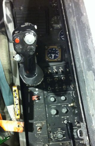
I get the impression through reading docs that the stick could have a very slight rotation, but not noticeable just by eye (as you can see in the picture above), I would say 5 degrees or less but in NO case is following the 12 degrees of the sensors.
I hope that helps
Cheers
Tulkas
-
-
Amraam, what is PTC?
Pilot training course. It’s a cd given to the pilot when he start training on the F-16. In fact, this is a dash one manual with some other information.
Edit: hehe, good shoot raptor!
-
My friend is a FLCS specialist and I will talk to him too.
I have many Dash1 here + other MLU/BLK 50+ manuals, and I don’t see in any of the that the stick is twisted, but I can read that the newer BLK´s got there transducers twisted.
Please point me to the pages that show the stick twisted 12 degree.Kukki
we dont need information about FLCS… i got everything
")
-
@Mav, it turns that the SCC and stick are actually aligned properly, the internal SCC sensors however have the 12deg cw positioning. Is is logical due to the wrist joint with the physical arm positioning that if pulling back the stick will give a physical wrist movement to actually the ~7 o’clock axis.
This weekend I will be close to rl so I’ll find out more. Don’t completely count on the manual, specially -1, as to other details it leaves this deeper details in black, no need for the passenger to know more. One would need access to the FLCS maintenance ppl to find out the answers.
sorry but this makes no sense at all
in amraam picture, the whole stick is clearly rotated.
in the quotation of the dash1, it is clear that the stick is rotated, not the sensors.
and if sensors were rotated, what if you put roll only ? then you will have pitch mixing as well ? WEIRD !
-
Roll and pitch axes is rotated.
-
……and the Pitch transducers in the BLK 10 Stickbase is NOT angled those 12 degree, but they are in the BLK 52 stick base, …
The BLK52 has a digital FLCS with a rudder stability augmentation system (SAS)? And the BLK 10 has a analog FLCS without rudder SAS and it also has a larger vertical stabilizer? iirc.
So the stick sensor could be rotated to add roll to correct for rudder to roll coupling when crabbing, caused by engine gyroscopic forces during pitch change, is corrected by the digital FLCS rudder SAS. LOL, it sounds thin.
If the engine acts like a gyroscope, a force equal to the to the force that is applied to the engine to rotate is also applied to the axis 90* to the engine turbine axis. This is the yaw axis. So engine gyroscope effect causes the a/c to crab. The digital FLCS will correct this crab with rudder, the analog FLCS does not. With a rudder command, there is some roll compiling. Nothing in the FLCS solves for rudder to roll coupling(only has rate dampening).
-
@Mav, it turns that the SCC and stick are actually aligned properly, the internal SCC sensors however have the 12deg cw positioning. Is is logical due to the wrist joint with the physical arm positioning that if pulling back the stick will give a physical wrist movement to actually the ~7 o’clock axis…
Thiers only 1/4 inch of travel in the stick. Anything having to do with the arm’s rotary to linear motion wouldn’t be a factor imo if I’m understand you.
Also the arm rest is there to kept the pilot arm in axis. Is their a procedure that says the pilot need to set the arm set 12* to the stick?
-
Damn this here is getting technical
but we like it… hehe -
just seen some pics i took of a blk52+ and the stick indeed is leaning forward…
In my setup I have already applied it to my cougar instalation as for hardware… the solution is in the spirit of pistolero… tommorow i will post some pics and will check for software problems cause of force sensors…
HOT LIST

System Specs:
i7-2600K @ 4.8 Ghz WaterCooled / 32GB Ram. 128GB SSD/1TB SSD / GTX1080Ti 11GB DDR5X / HOTAS COUGAR. TrackIR 4 / 3x24" Mon. (res:5760x1200) / Cougar MFD's / Wheel Pedals / Win 10 64 bit.

-
The BLK52 has a digital FLCS with a rudder stability augmentation system (SAS)? And the BLK 10 has a analog FLCS without rudder SAS and it also has a larger vertical stabilizer? iirc.
So the stick sensor could be rotated to add roll to correct for rudder to roll coupling when crabbing, caused by engine gyroscopic forces during pitch change, is corrected by the digital FLCS rudder SAS. LOL, it sounds thin.
If the engine acts like a gyroscope, a force equal to the to the force that is applied to the engine to rotate is also applied to the axis 90* to the engine turbine axis. This is the yaw axis. So engine gyroscope effect causes the a/c to crab. The digital FLCS will correct this crab with rudder, the analog FLCS does not. With a rudder command, there is some roll compiling. Nothing in the FLCS solves for rudder to roll coupling(only has rate dampening).
dont know for block 10 but since block15, all FLCS (analog or digital ) have the same components (including SAS)
-
dont know for block 10 but since block15, all FLCS (analog or digital ) have the same components (including SAS)
As long as you don’t say digital AND analog FLCS.
The ECA was removed as a separate box and incorporated into the DFLCC for digital flight controls. The inverter/battery assemblies were also removed going from analog to digital FLCS.
-
This post is deleted! -
Advancing throttle on the ground for increasing taxi speed produces a right roll force that will drop the right wing few inches vs lift left side, and slightly turn the nose to the left. Small pedal inputs required to maintain a straight ride, except if you pull back throttle to idle and let the sufficient thrust to let move the bird.
On air this engine gyro effect is auto corrected by flcs.
-
On air this engine gyro effect is auto corrected by flcs.
I worked the F-16 for 19 years and never heard of this and also just double checked the FLCS CDCs. They don’t mention one word about FLCS adjustments for engine gyroscopic effect. The only adjustment it talks about for outside influences like this is the gun compensation logic.
-
Don’t know of the tech gizmos details or special documentation that you might have available, just the above link and a great hud/helmet vid with a sq commander describing this effect on ground, as it is happening on the taxi roll. I have mentioned this “feature” in the past too. (I am not 100% sure for the bank direction though, have to review it).
-
dont know for block 10 but since block15, all FLCS (analog or digital ) have the same components (including SAS)
I got a other stuff backwards.
The bigger vertical fin came on the later blocks for more stability when LANTIRN pod equiped . -
Don’t know of the tech gizmos details or special documentation that you might have available, just the above link and a great hud/helmet vid with a sq commander describing this effect on ground, as it is happening on the taxi roll. I have mentioned this “feature” in the past too. (I am not 100% sure for the bank direction though, have to review it).
Try re-reading what I wrote and go again. I didn’t say the effect didn’t exist. I stated that the FLCS training I got and the documentation I have doesn’t mention ONE word about it. Thus the FLCS is NOT auto adjusting for this. If it was there would be logic in the DLFCC that could possibly go bad thus requiring troubleshooting of the problem. The maintainers would know about it and it would be documented in CDCs, flight manuals, etc.
