Another Hall Sensor upgrade
-
As soon as the kids are done with college and the dog dies we will be considering it. I know my wife is up for it. As long as I have a place for my CNC machines I will be happy. My Army pension go’s with me anywhere, but we would loose our military healthcare.
edited
just found out they have a program for expats. hmmmmmm -
Ya know, i was successful with installing and centering the sensor to magnetic ring without the instructions. Just used common sense and symmetry. Moving the throttle throw fully back and forth, i marked with a sharpie where the sensor should be on the middle of the core and tightened it down. The center of the ring corresponded with the throttle handle being perpendiclar with the base (symmetry). I chose the unopened side of the ring magnetic core to face the sensor because thats less likely to snag on the sensor pcb (if i was wrong, pretty sure the throttle would be inverted or not work at all). The gap distance was small enough to move freely (about a dime to a nickel’s thickness). I did have to unloosen the two screws holding the sensor pcb to its mounting bracket and realign it to be parallel with the face of the magnet ring, then retighten it. It was slightly off.
Going back to Miles’ videos now, i can see the first throttle video doesnt go deep into using symmetry to get a first pass at ring alignment, but otherwise it looks fine. Also, im not sure what TM utility he was using for alignment. I used the TM CCP as pictured above. Both work.
In the second throttle video, which shows how to “calibrate” the upper and lower dead space out of the throttle’s full movement. What Miles is showing is how to effect the magnetic coupling between the magnet ring and Hall Sensor solely by adjusting the gap between them mechanically. Due to hysteresis, if the gap is too close, the upper and lower areas on the throttle throw are saturated and it has like a dead zone on either end. Increasing the gap will reduce these dead zones. Thats the calibration method Miles is showing.
Another method that can be used separately or in conjunction with this gap method, is to recalibrate the TQS in the TM CCP utility or the Realsimulator TUSBA utility. The gap method could be a course and the utilities a fine calibration methodology.
-
Since I have trouble understanding your terminology (English is not my mother language) could u be so kind and in your pic add arrows of what is what?
About using the not opened side I believe once I get it I will understand it?
Sent from TapaTalk
HOT LIST

System Specs:
i7-2600K @ 4.8 Ghz WaterCooled / 32GB Ram. 128GB SSD/1TB SSD / GTX1080Ti 11GB DDR5X / HOTAS COUGAR. TrackIR 4 / 3x24" Mon. (res:5760x1200) / Cougar MFD's / Wheel Pedals / Win 10 64 bit.

-
Well this what the Miles TQS hall sensor mod contains:
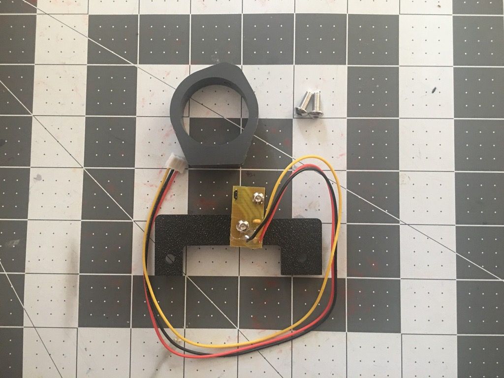
The magnetic core ring is shown with the plastic side that covers the 4 small rare earth magnets in series. This is the side to face the Hall Sensor device. The opposing side has no plastic covering the magnets and is how Miles inserted them.
Looks like he used a 3-D printer to make this ring and the pcb bracket. If so, these are soft plastics so dont over tighten the ring set screw. If you look closely, you can see the pcb is slightly askew angle wise from the base bracket. These two screws can be used to make the sensor perfectly perpendicular to the magnetic ring once its mounted on the throttle barrel.
-
Hey AV8R,
The magnet ring is CNC machined PVC and the mounting bracket is machined out of ABS. Its a long set screw so it would be hard to strip, but yes, I would be careful not to overtigthen. While I have a 3d printer I would not trust it for production.
Thanks for the feedback, -
Some guys have all the kewl toys
-
As a 18Z in the U.S. Army I had all the cool toys and got to travel around the world and play with them. Now I just make stuff in my basement.
-
I changed from boxes to padded envelopes for international shipping, Its less expensive and seems to make customs go quicker. The downside is the sensor bracket and spacers come dissembled. This pic should be self explanatory. Just make sure the solder joints line up with the relief cuts in the spacer.
Thanks -
My 2 euros worth…
The Hall Sensors and capacitor need to be protected from impact and crushing that a padded envelope isn’t structurally sound for.
1. Put some kind of rigid cap over them
Or
2. Cut their leads down to where they are basically SMDs.
Or
3. Bend the Capacitor over flush with the pcb, and put a 3-lead socket on the pcb and let the customer plug the 3 lead sensor into it when assembling. This way it’s not crushable. Might add a buck to the cost, but it’s better than having to deal with returns.https://octopart.com/917-93-103-41-005000-mill-max-853810
Or
http://www.jameco.com/webapp/wcs/stores/servlet/ProductDisplay?storeId=10001&productId=164822&catalogId=10001&langId=-1&CID=GOOG&gclid=CjwKEAjw5vu8BRC8rIGNrqbPuSESJADG8RV0cO-Ixjvq5pdzUJq1Bs1mRHU-QuTkUmdPxzPVWTwyNRoCPlnw_wcBI do admit that I liked the box because it works perfectly to hold the TQS upside down when working on a table.
")
AV
-
What are relief cuts?
Sent from TapaTalk
HOT LIST
System Specs:
i7-2600K @ 4.8 Ghz WaterCooled / 32GB Ram. 128GB SSD/1TB SSD / GTX1080Ti 11GB DDR5X / HOTAS COUGAR. TrackIR 4 / 3x24" Mon. (res:5760x1200) / Cougar MFD's / Wheel Pedals / Win 10 64 bit.
-
:lol: just arrived today…
The local mail tracking system is not connected with the US originating one (Yeap Greece I know) and I just received a txt msg from my buddy at post office that I have a package waiting…
:lol: oh Santa is here on August…
HOT LIST
System Specs:
i7-2600K @ 4.8 Ghz WaterCooled / 32GB Ram. 128GB SSD/1TB SSD / GTX1080Ti 11GB DDR5X / HOTAS COUGAR. TrackIR 4 / 3x24" Mon. (res:5760x1200) / Cougar MFD's / Wheel Pedals / Win 10 64 bit.
-
Good to hear this Arty! Enjoy the mod!!!
-
Now someone please fast forward the clock to 18:30 and bring me the teleportation device at my office… :lol:
Thankfully next week I have a vacations leave and I will be without kids at home… Ohhhh yeeeeaaaaaaa. AAR planes start your engines…
-
My 2 euros worth…
The Hall Sensors and capacitor need to be protected from impact and crushing that a padded envelope isn’t structurally sound for.
1. Put some kind of rigid cap over them
Or
2. Cut their leads down to where they are basically SMDs.
Or
3. Bend the Capacitor over flush with the pcb, and put a 3-lead socket on the pcb and let the customer plug the 3 lead sensor into it when assembling. This way it’s not crushable. Might add a buck to the cost, but it’s better than having to deal with returns.https://octopart.com/917-93-103-41-005000-mill-max-853810
Or
http://www.jameco.com/webapp/wcs/stores/servlet/ProductDisplay?storeId=10001&productId=164822&catalogId=10001&langId=-1&CID=GOOG&gclid=CjwKEAjw5vu8BRC8rIGNrqbPuSESJADG8RV0cO-Ixjvq5pdzUJq1Bs1mRHU-QuTkUmdPxzPVWTwyNRoCPlnw_wcBI do admit that I liked the box because it works perfectly to hold the TQS upside down when working on a table.
AV
Great point, I actually place the sensor inside the throttle ring where it is protected.
-
Arty,
I think yours may have been one of this first ones shipped in the padded envelope and I put the wrong sensor in it. The next day I shipped out the correct sensor. You should have received 2 tracking numbers. Hopefully the correct sensor comes today also. -
I got only one tracking number.
:lol: talk about luck…
Let’s see maybe they packed them together…
In a few hours I’ll tell’ya.
Sent from TapaTalk -
Is this the correct MilesD:

???
click to enlarge.
It has a letter on top I can’t recognize
and the number must be 325.HOT LIST
System Specs:
i7-2600K @ 4.8 Ghz WaterCooled / 32GB Ram. 128GB SSD/1TB SSD / GTX1080Ti 11GB DDR5X / HOTAS COUGAR. TrackIR 4 / 3x24" Mon. (res:5760x1200) / Cougar MFD's / Wheel Pedals / Win 10 64 bit.
-
I am sorry to say that one is for the joystick. I thought I may have done that. You should get the correct board tomorrow. Don’t plug that in, its wired differently.
-
Overall time of delivery and the whole experience with MilesD and his kindness and service was way more than ok.
27/7 sent 2/8 received.The Packaging way small and rigid.

2 paper cardboard’s to safeguard it from stress of going to a bankrupt country… :lol:

The inner second stage safety… all taped with a non leaving glue navy blue tape… (I love this color…)

The product with the sensor carefully placed in the safety of the plastic ring… No way it can get heart… It must brake the way strong ring first.

Yeap we are there…

And the sensor and the socket for the pcb…

Thanx MilesD… One happy customer here…
And that concludes the final current version of unboxing MilesD HallSensor for Cougar Throttle new special packaging …
Thank you all for watching.
HOT LIST
System Specs:
i7-2600K @ 4.8 Ghz WaterCooled / 32GB Ram. 128GB SSD/1TB SSD / GTX1080Ti 11GB DDR5X / HOTAS COUGAR. TrackIR 4 / 3x24" Mon. (res:5760x1200) / Cougar MFD's / Wheel Pedals / Win 10 64 bit.
-
Well if it’s just soldering I have the tools and soldering skills…
Edit: Oh what I’m saying… it must be past midnight there… Go sleep m8 I’ll wait til tomorrow.
HOT LIST
System Specs:
i7-2600K @ 4.8 Ghz WaterCooled / 32GB Ram. 128GB SSD/1TB SSD / GTX1080Ti 11GB DDR5X / HOTAS COUGAR. TrackIR 4 / 3x24" Mon. (res:5760x1200) / Cougar MFD's / Wheel Pedals / Win 10 64 bit.