WIP: F-14 B/D
-
About 3-4 weeks…
Would those be Falcon Weks, or Tomcat Weeks?

But seriously, Geat work as always.
-
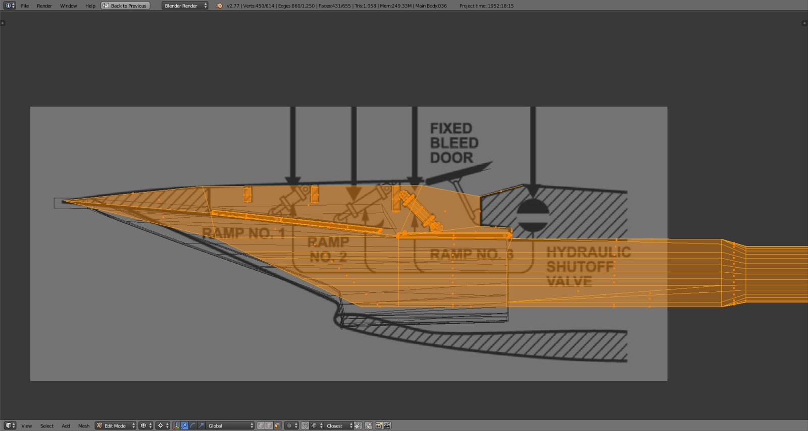
Look closely it’s already modeled including the two square blocks on the ramp
")
Of course i noticed that, but, if i’m not mistaking ;), it looks like you’ve inverted the actuator pushing the last ramp (biggest cylinder’s body is at the top IRL)
Thank’s for efforts -
@SEG:
Of course i noticed that, but, if i’m not mistaking ;), it looks like you’ve inverted the actuator pushing the last ramp (biggest cylinder’s body is at the top IRL)
Thank’s for effortsOk now I get it. This seems to be a visual distortion, check this image
And this:
It could be that the NASA drawing has the wrong angle (which I doubt) but in general thickness and proportion is correct. What might distort the look is that the cylinder is completely inside the actuator strut thereby making it look thicker. Once the ramp is rigged the cylinder will extrude out of the strut and the entire actuator rotates toward the front along the top hinge point inside the inlet.
Also the shading of the actuator is currently flat, making it look even thicker than it is.
Hope this clarifies if not, please let me know.
-
Would those be Falcon Weks, or Tomcat Weeks?
But seriously, Geat work as always.
Is there a difference?
")
-
Is there a difference?
Yes…
Tomcat Weeks are longer than Falcon Weeks as per till now observations… :lol:
HOT LIST

System Specs:
i7-2600K @ 4.8 Ghz WaterCooled / 32GB Ram. 2TB SSD/1TB SSD / 20TB HDD Total / GTX1080Ti 11GB DDR5X / HOTAS COUGAR. TrackIR 4 / 3x24" Mon. (res:5760x1200) / Cougar MFD's / Wheel Pedals / Win 10 64 bit.

-
Ok now I get it. This seems to be a visual distortion, check this image
You right, it must be a distortion (Nasa putted it in the same way).
Sorry, I didn’t want to be annoying
-
@SEG:
You right, it must be a distortion (Nasa putted it in the same way).
Sorry, I didn’t want to be annoyingAll good! All constructive criticism and observations are ALWAYS welcome and appreciated.
Let’s take another look at it once it’s rigged and fully deployed, then I’ll refine the details and hinge points.
I was wrong on the drawing that’s from the NATOPS manual not from NASA. My original Grumman blueprints actually show an actuator that is tilted in the other direction but that might be another actuator as the drawings are extremely convoluted.
-
Hi Stingray_SIX_TWO.
I follow the your work with great pleasure and impatience. When it’s over, it’s gonna be a perfect plane. I’m sure of that.
Do you plan to make the F14 cockpit after you finish the exterior model? If you do the cockpit, the community will be grateful.:bdance:
Best regards.
Burak
If (IF!) I survive the modeling, tex mapping and 3DS stuff in terms of DOFs etc. and it’s flyable and functional then that will probably be a confidence booster which might lead me to believe that I could embark on something like building a pit.
Long ways…
-
-
I believe you can do it. I’m sure of that.
Best regards.
-
My original Grumman blueprints actually show an actuator that is tilted in the other direction
That was my guess too
As you said, best view is with the supersonic aperture configuration -
@SEG:
That was my guess too
As you said, best view is with the supersonic aperture configurationTrust me, it’s modeled correctly. Look at the airflow diagram:
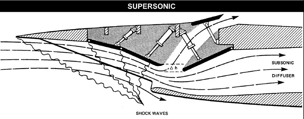
Any other positioning of the cylinder wouldn’t make sense from a structural and pressure standpoint. The way it is designed is to minimize the amount of force the hydraulic pressure has to overcome while at the same time ensuring a solid and undisturbed base of the actuator and to minimize it’s drag in the inlet. Now turn that actuator around and you’ll see what the problems would be.
-
Keep the AICS actuators as they are : It must be a question of perspective :rolleyes:
-
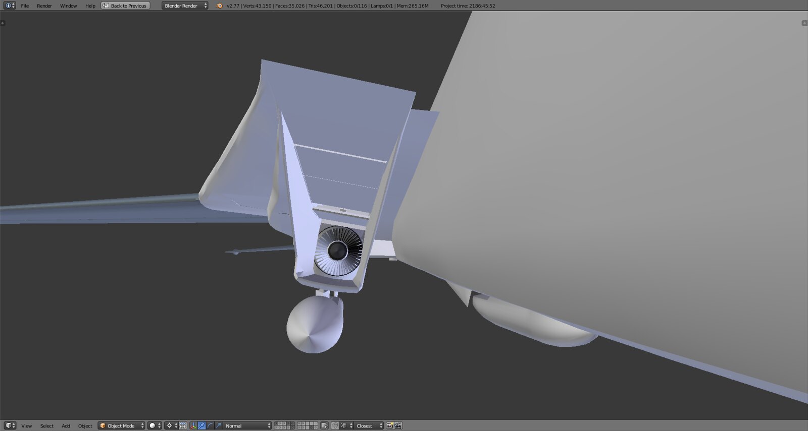
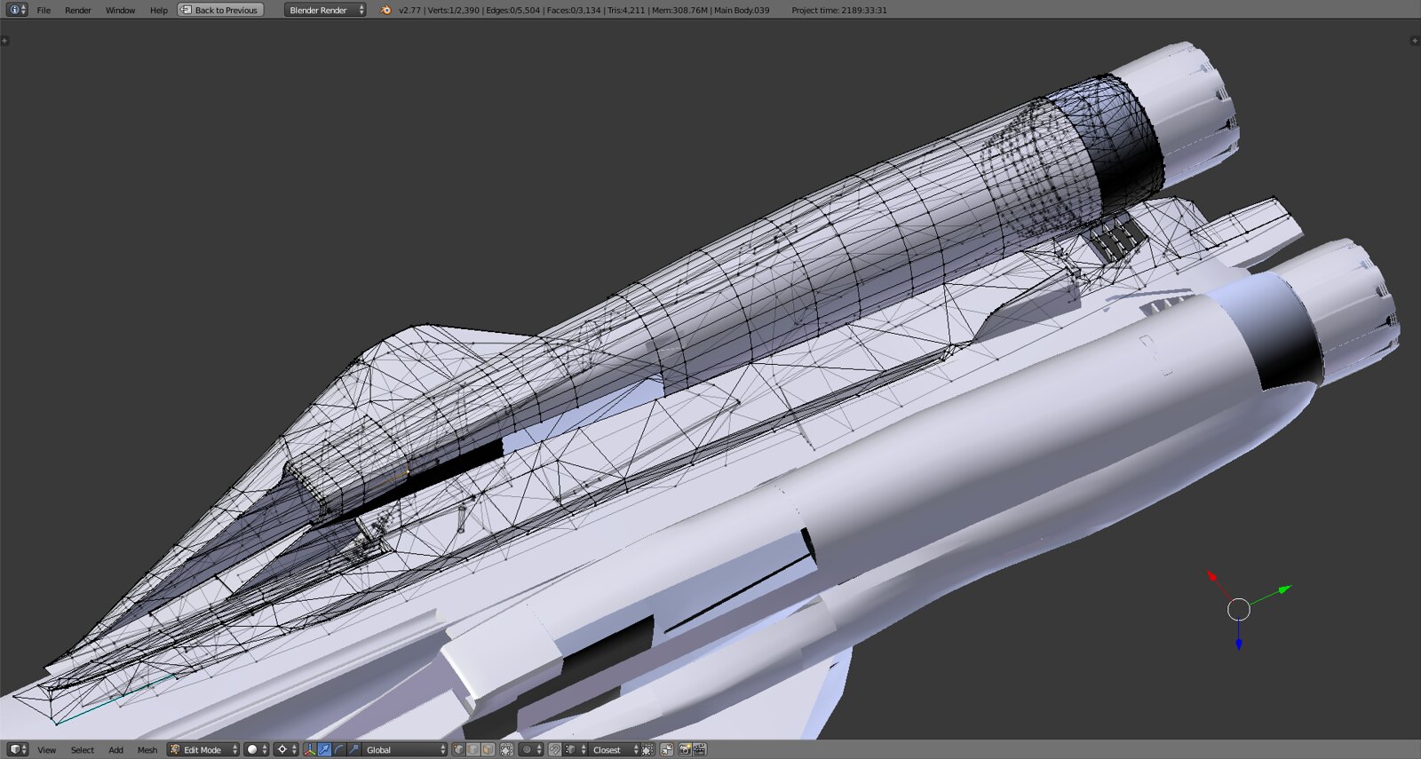
Anyone need a jet engine or two?
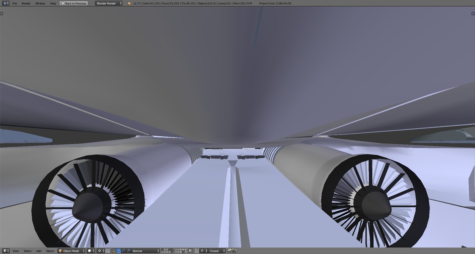
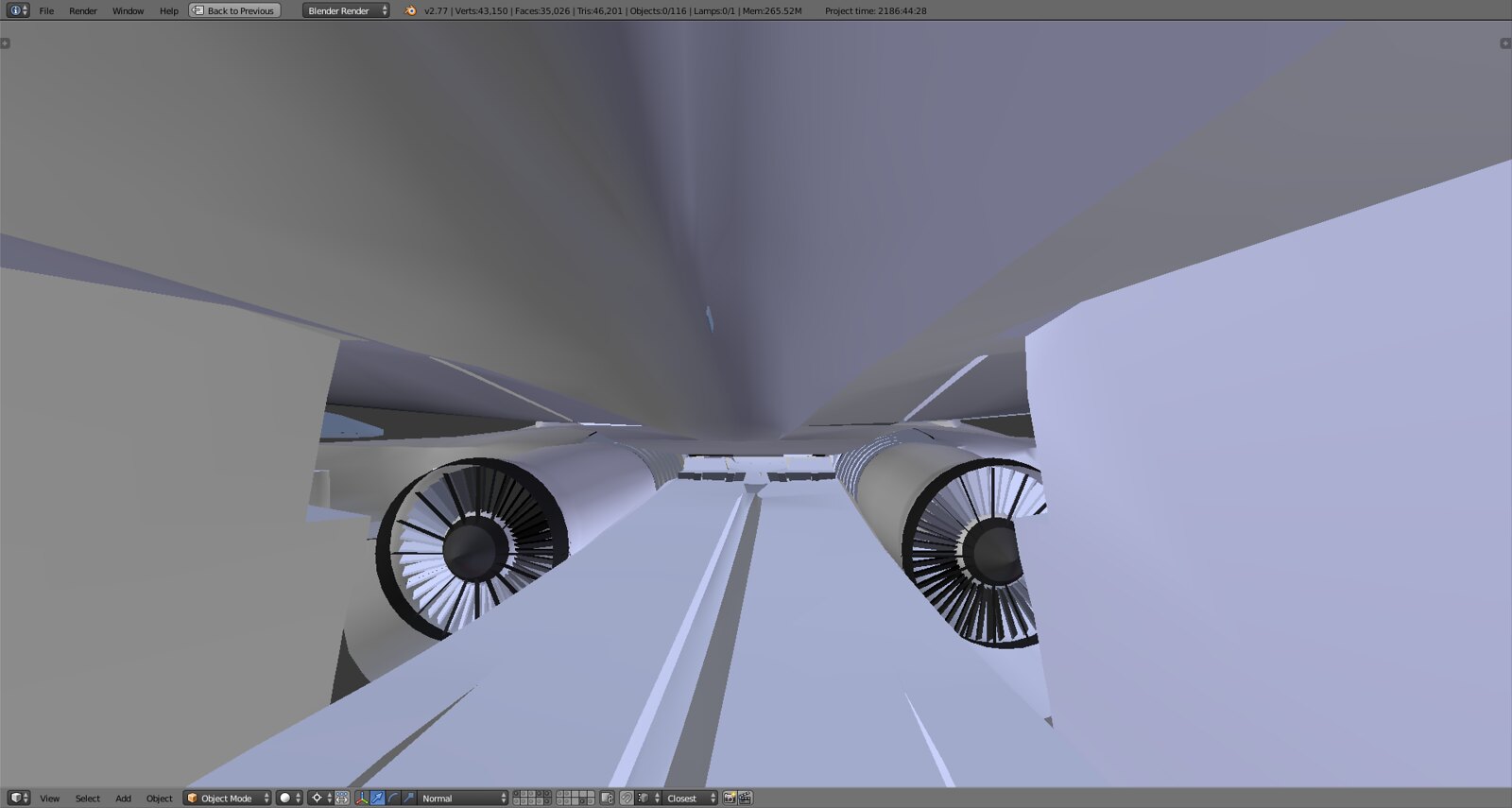
As always in this business you find yourself needing to model everything in order to model everything else otherwise you have no realistic scale and reference so I built the GE F110. Characteristically much shorter than the original P&W F-111 leftovers.
Engines sit slightly tilted inward around 3 degrees.
Attaches pretty well to the shroud and nozzle as well as the intake.
Don’t get sucked inthere…
As you can see the engine pod is in rebuilt stage, currently attaching intakes to the pod. It now also has the characteristic shape of tilting slightly inward and then out to round off toward the center of the plane.
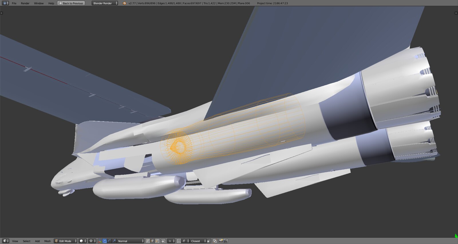
F110-400, Baby.
-
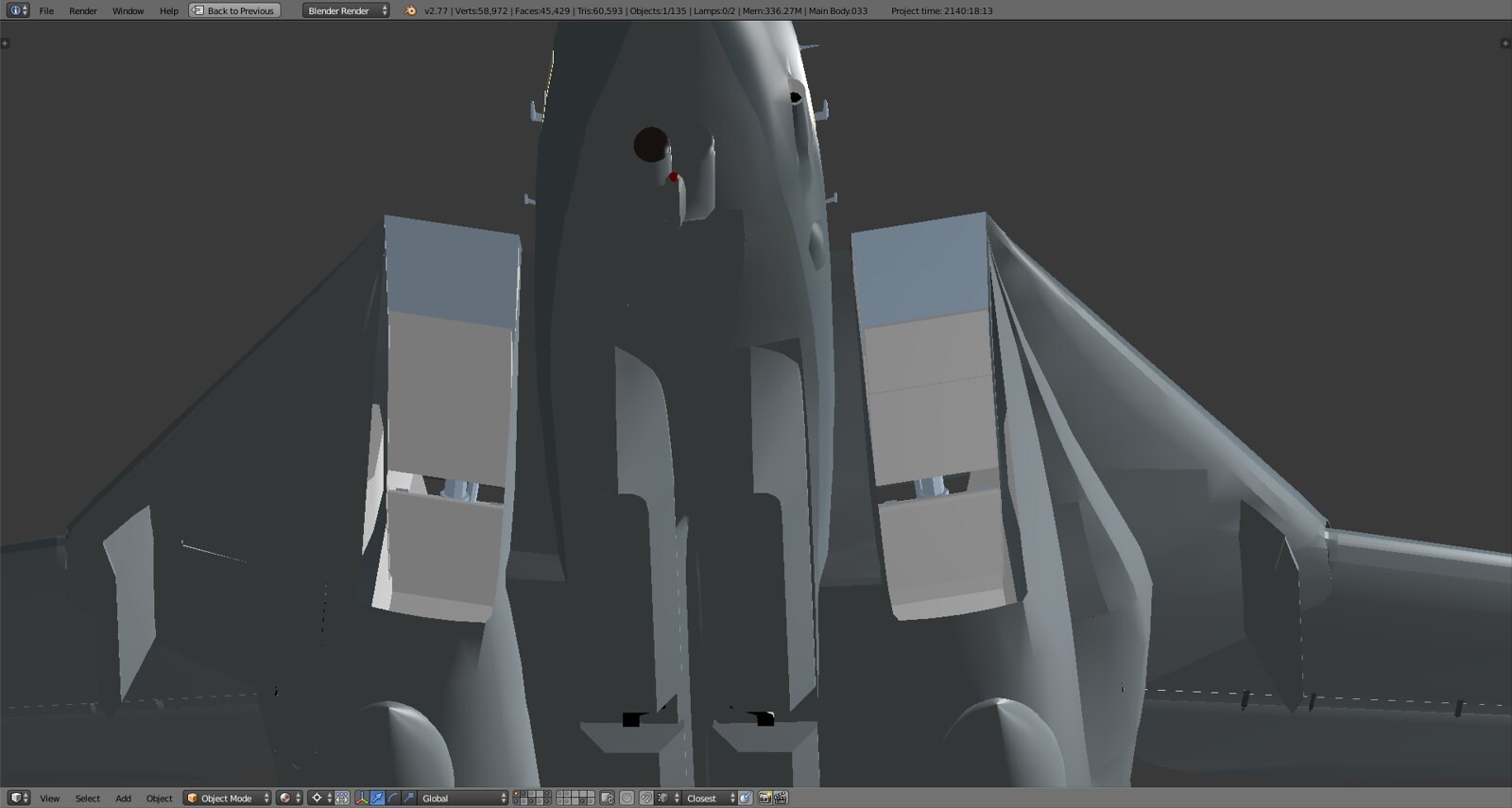
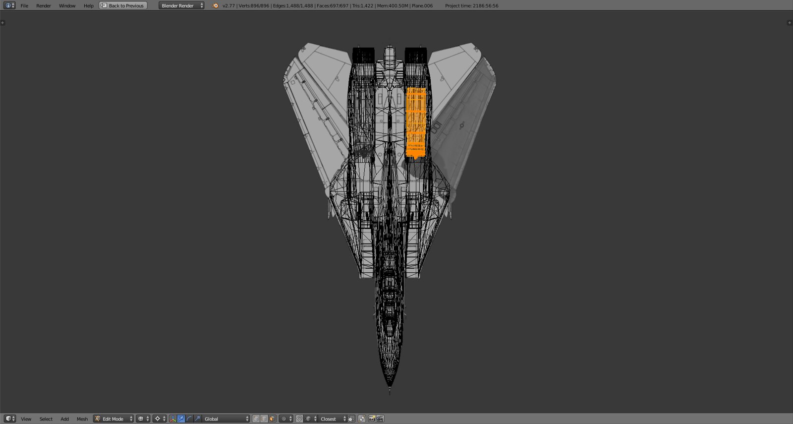
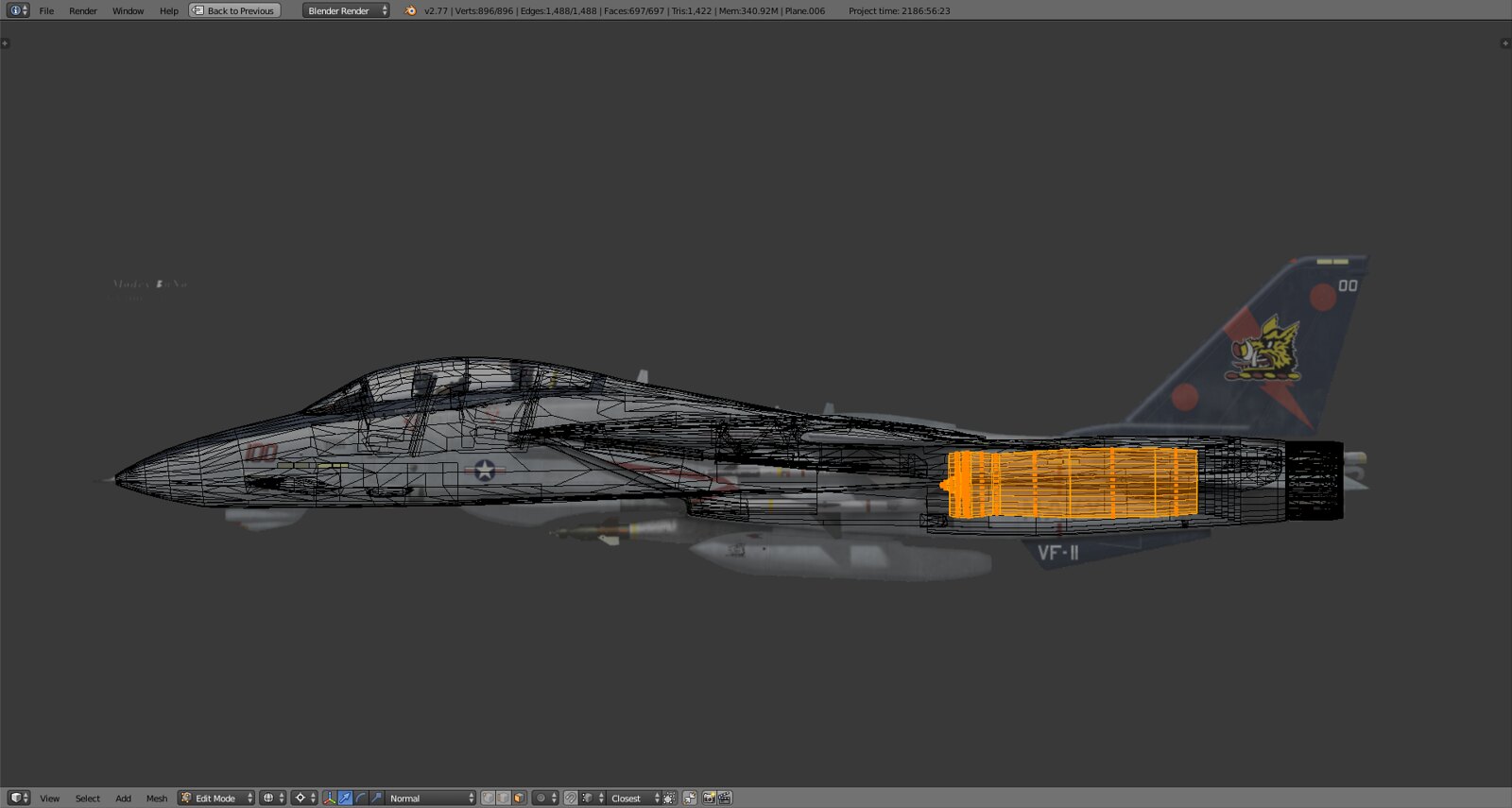
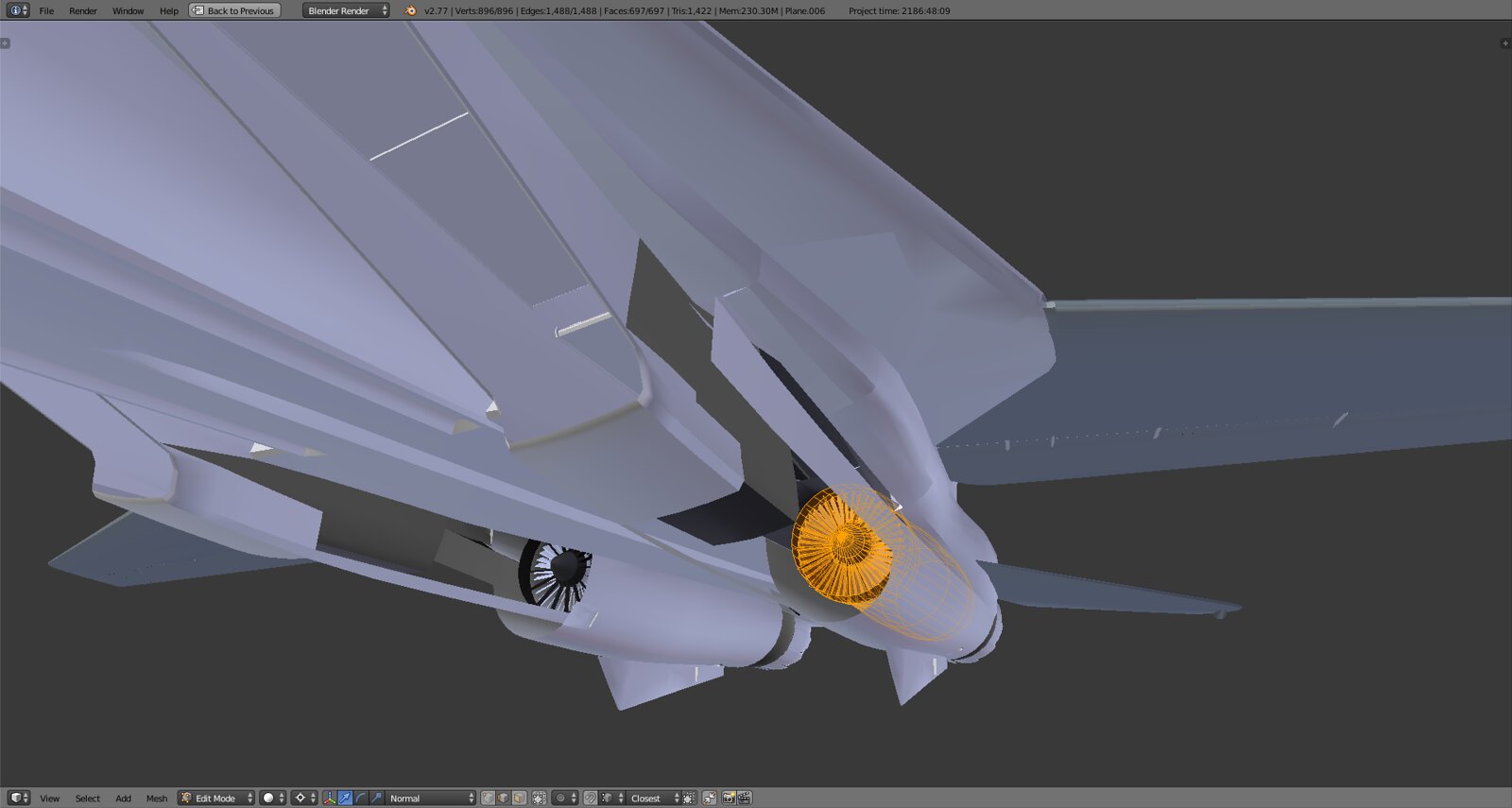
Beaver will love this…aaaaall squares :). You can already see the silky smooth surface. Still finalizing the front end transition from square inward tilting intake to round engine pod.
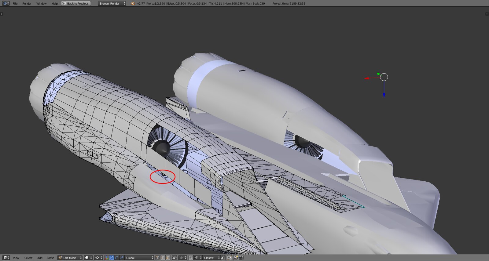
Red circle marks the difference between the new ‘beltline’ and the old one. Basically the intakes were too narrow and sat too far inward and the shape didn’t make that outside in turn. Hence the intake and the engine face were misaligned aaaaand the entire pod was way too thick on the outside. Will have to correct the main landing gear doors. By the way this also explains why the MLG wouldn’t fit even though it was perfectly modeled to scale - there just wasn’t enough room in the fuselage due to my faulty line.
The front fuselage will get the same corrective surgery treatment once the bottomside is done.
-
Rebuilding those areas after having spent soooooo many time in modelling them must be…:uham:
So : >>>>>
-
THANK YOU FOR BEING SUCH A RIVET COUNTER!!! We need those big fat intakes to scare the crap out of the enemy when they see us on their six! Makes them feel like our engines will eat them if our weapons don’t first!(true IRL statement from an F-16 guy after getting beat by an F-14 Veteran-flight hours made the difference in this scenario)
-
THANK YOU FOR BEING SUCH A RIVET COUNTER!!!
You know it man. Only way to go about this, it deserves nothing less. Thing is with the details it just adds up in terms of geometry, 2000 for the pit, 2000 for the engines, another 2000 additional tris for the engine pods. I’m rapidly moving up on 70k excluding AB. Upside is that the model will have a level of detail and accuracy that exceeds that of other ones out there (not mentioning names here) with at least double the poly count. Doesn’t help but it feels good :).
flight hours made the difference in this scenario)
Don’t they always…
-
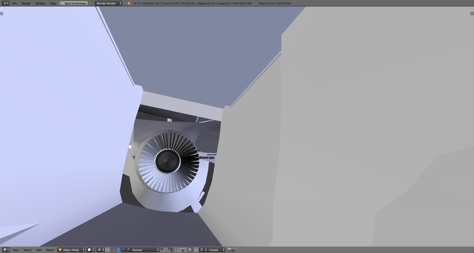
Some matcap shaded shots. Slowly getting the alignment intake-engine-shroud/nozzle right.
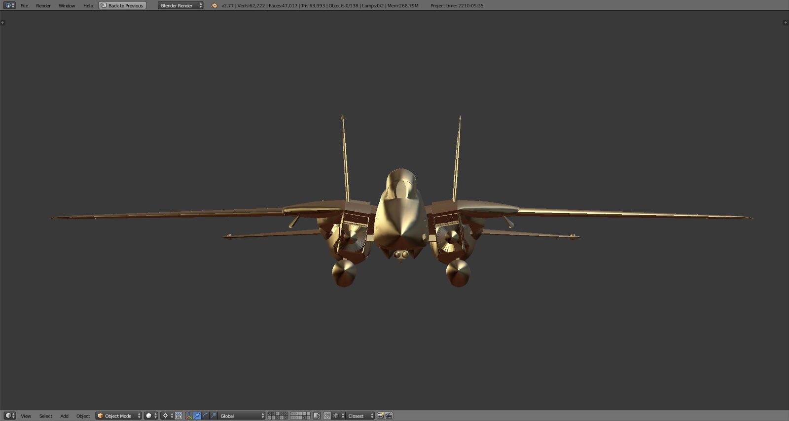
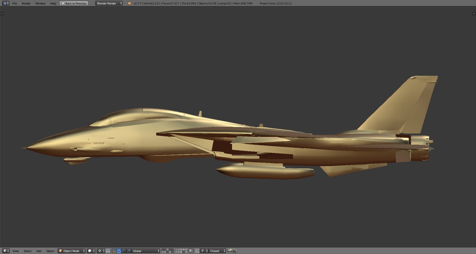
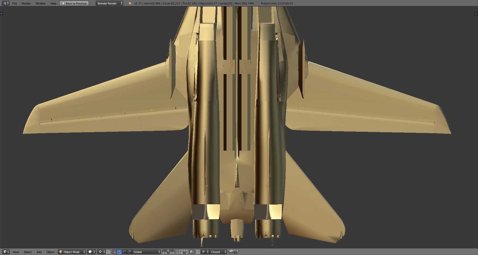
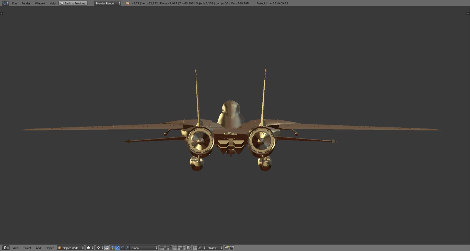
Engines, intakes, nozzles and ramps are at the moment within 95% authentic scale. So anything from here on out is more of an alignment within the ~5% range instead of a major correction. The inside walls of the inlet are not yet finalized.