Another Hall Sensor upgrade
-
I have had a few customers that have had issues with windows not reading the hall sensor. In doing some research into this it appears there is 2 boards for the cougar throttle a 3.8 volt and 5 volt version. The 5 volt appears to be the newer one. While I have been unable to confirm it yet it looks like this may be the problem. Before anyone else orders the kits I would check to make sure you have the newer board.
New board (AV8R Pic)
New board board Back
Old board not compatible (from scubapic)
Since I am new at this if anyone has more information on this, please tell
Thanks
Miles -
ok the correct sensor arrived let’s hope the pcb is the correct one.
HOT LIST

System Specs:
i7-2600K @ 4.8 Ghz WaterCooled / 32GB Ram. 128GB SSD/1TB SSD / GTX1080Ti 11GB DDR5X / HOTAS COUGAR. TrackIR 4 / 3x24" Mon. (res:5760x1200) / Cougar MFD's / Wheel Pedals / Win 10 64 bit.

-
There’s at least two workarounds for this situation where one pcb gives 3.8 and the newer gives 5.0 vdc. (Noting the hall sensor requires a minimum of 4.5 vdc to operate)
1. Use a jumper wire from 5.0vdc on the TM PCB to feed the Miles PCB and Hall sensor. There’s a couple of ways to do this, one cutting a PCB trace (Solkol1’s idea) and another re-routing the jumper wire directly to power pin on the Miles pig tail cable (AV8R).
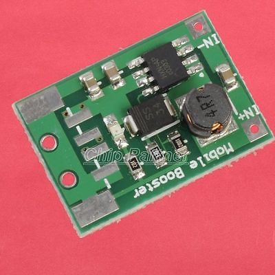
2. Add a mini DC-DC 3.8 to 5.0 vdc step up converter. Cost a few bucks and could be done to still make Miles mod be plug and play.
Where red there is a will and information, there is a way.
-
Here is the original post on how to possibly fix this from scubapic.
https://www.benchmarksims.org/forum/showthread.php?24707-Cougar-Throttle-Hall-Effect-Potentiometer-Cubpilot-Reincarnated!&highlight=cub+pilot -
Or use a usb charge or usb cable (connected to a powered usb plug) cut the wire isolate the power line wire and plug it to miles pcb? Could this also work?
Sent from TapaTalk
-
That would work, but it’s overkill as the 5vdc is already on both versions of the TQS PCBs. It’s just a matter of supplying the power (proper voltage without too much current than the device can handle). A jumper wire and trace cut or an onboard mini dc-dc converter would be simpler and without more external wires and power supplies.
Also, the PCBs have a version/revision number on them, and I bet TM knows what TQS serial numbers were run for each PCB version. This would allow people to know which pcb type without opening up the base. But once the TQS base is opened up, and it has to eventually, one can read the pcb version and inspect the pcb for the series surface mounted resistor.
-
This post is deleted! -
Yeap I understand but I don’t like messing with the Cougar pcb…
NOW PLEASE DOCTORS TELL ME:

WILL IT LIVE?
:???::???::???::?::?::?:

HOT LIST
System Specs:
i7-2600K @ 4.8 Ghz WaterCooled / 32GB Ram. 128GB SSD/1TB SSD / GTX1080Ti 11GB DDR5X / HOTAS COUGAR. TrackIR 4 / 3x24" Mon. (res:5760x1200) / Cougar MFD's / Wheel Pedals / Win 10 64 bit.
-
Arty
It looks like you have the new board. Did you try it yet? -
Great news… I too am a long time modded Cougar guy with the Evenstrain mod which is working just fine at the moment. This looks like a mod for a Stock Cougar. My question is does this mod help when the stock gimbals start to wear. I do know the stock gimbals are made of a softer metal and over time some slop will happen and this is what put uneven strain on the POTS which would wear them out quick. It looks like this mod has no contact with anything so I’m assuming it addresses this old issue.
-
Arty
It looks like you have the new board. Did you try it yet?Not yet. It arrived a bit late and I was already at work… Probably Tomorrow…
HOT LIST
System Specs:
i7-2600K @ 4.8 Ghz WaterCooled / 32GB Ram. 128GB SSD/1TB SSD / GTX1080Ti 11GB DDR5X / HOTAS COUGAR. TrackIR 4 / 3x24" Mon. (res:5760x1200) / Cougar MFD's / Wheel Pedals / Win 10 64 bit.
-
I hate cliff hangars
:munch:
-
Miles why do I have 2 plastic pieces? I should put them underneath the hall sensor pcb?
Ok disregard I found the video…
HOT LIST
System Specs:
i7-2600K @ 4.8 Ghz WaterCooled / 32GB Ram. 128GB SSD/1TB SSD / GTX1080Ti 11GB DDR5X / HOTAS COUGAR. TrackIR 4 / 3x24" Mon. (res:5760x1200) / Cougar MFD's / Wheel Pedals / Win 10 64 bit.
-
Yes this picture should show how.
-
The spacers are there to make sure the height is correct and provide a relief cut so the board can sit flat. Just be sure the solder joint is in the relief cut.
-
Thanx I figured it out as it was the only way to assemble them. :lol:
Sent from TapaTalk
HOT LIST
System Specs:
i7-2600K @ 4.8 Ghz WaterCooled / 32GB Ram. 128GB SSD/1TB SSD / GTX1080Ti 11GB DDR5X / HOTAS COUGAR. TrackIR 4 / 3x24" Mon. (res:5760x1200) / Cougar MFD's / Wheel Pedals / Win 10 64 bit.
-
Out of pure luck no ring adjustment needed… first call was perfect. At least this is what the apps say… falcon will be the final judge…
Edit: if u r lucky… Falcon just doesn’t run.
Yeap.
Aaaahhhhhuuuuuuuummmmmm
Where is that fire hose?
Edit: Found it… well it’s alive… the force feedback from my wheel pedals suddenly got blocking 4.33 U1. Yeap it’s alive… it has it’s own character and it’s braking my nerves down… Ohhhh Microsoft…
HOT LIST
System Specs:
i7-2600K @ 4.8 Ghz WaterCooled / 32GB Ram. 128GB SSD/1TB SSD / GTX1080Ti 11GB DDR5X / HOTAS COUGAR. TrackIR 4 / 3x24" Mon. (res:5760x1200) / Cougar MFD's / Wheel Pedals / Win 10 64 bit.
-
Yeap me again…
After the steam gone and many hours and exercises of yoga to reach spiritual stability cause BMS is not running as it should.
In the BMS UI I observed that there was a dead zone in the start.
I had zero before doing the cougar manual calibration. I did the calibration and everything shows fine in CCP.
But in BMS controllers I move the throttle and the axis is not moving… after a while it wakes up. Also it reaches max way sooner, which is not the case in CCP.Let me first say that I use a trick in the profile with the shifted way to go to afterburner… hmmm maybe now I should remove this as it’s not needed any more with the Hall Sensor. I will look in to it today if the cougar programming is causing it but shouldn’t I have the same observations in CCP?
HOT LIST
System Specs:
i7-2600K @ 4.8 Ghz WaterCooled / 32GB Ram. 128GB SSD/1TB SSD / GTX1080Ti 11GB DDR5X / HOTAS COUGAR. TrackIR 4 / 3x24" Mon. (res:5760x1200) / Cougar MFD's / Wheel Pedals / Win 10 64 bit.
-
Arty,
How did you make out? I really like DIView for testing. I don’t use CCP but it should give you more direct values. -
well diview was not accurate at all as ccp was not accurate also. From Foxy the issue is obvious.
I don’t have the energy right now to redo. I took it for a spin as is and I found it smooth.
In aar it was way easier to keep up for speed…
but my stick center play needs to be worked again so i couldn’t fully enjoy it as i couldnt center with the tanker .HOT LIST
System Specs:
i7-2600K @ 4.8 Ghz WaterCooled / 32GB Ram. 128GB SSD/1TB SSD / GTX1080Ti 11GB DDR5X / HOTAS COUGAR. TrackIR 4 / 3x24" Mon. (res:5760x1200) / Cougar MFD's / Wheel Pedals / Win 10 64 bit.