WIP: F-14 B/D
-
Sting, from someone that loved the ship (with wings that is), from the early 80’s and that had such a great influense on many people (manga, anime, movies), I would really love to see your work finished. Take your time and enjoy yourself. Thank you.
Cheers~
-
+1 here. You find me fully agreed!!!
Nikos.It was on my to do list for at least 5 years, I figured it was about time. It is going to take months or maybe even years though. Objectives/features is what will take most of that time.
-
@Switch:
It was on my to do list for at least 5 years, I figured it was about time. It is going to take months or maybe even years though. Objectives/features is what will take most of that time.
Just make your path mate… Go forward :p.
And Thank you!!!
Nikos. -

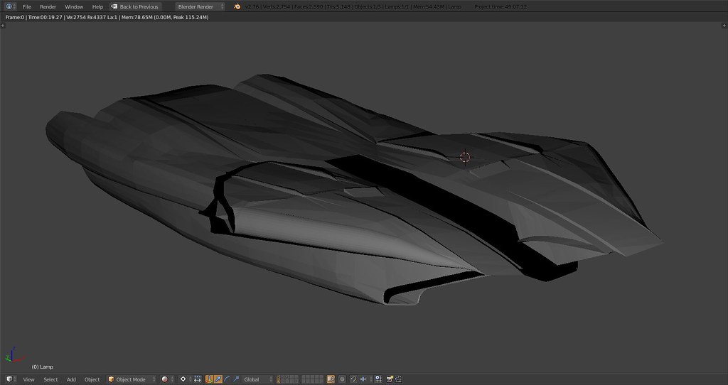
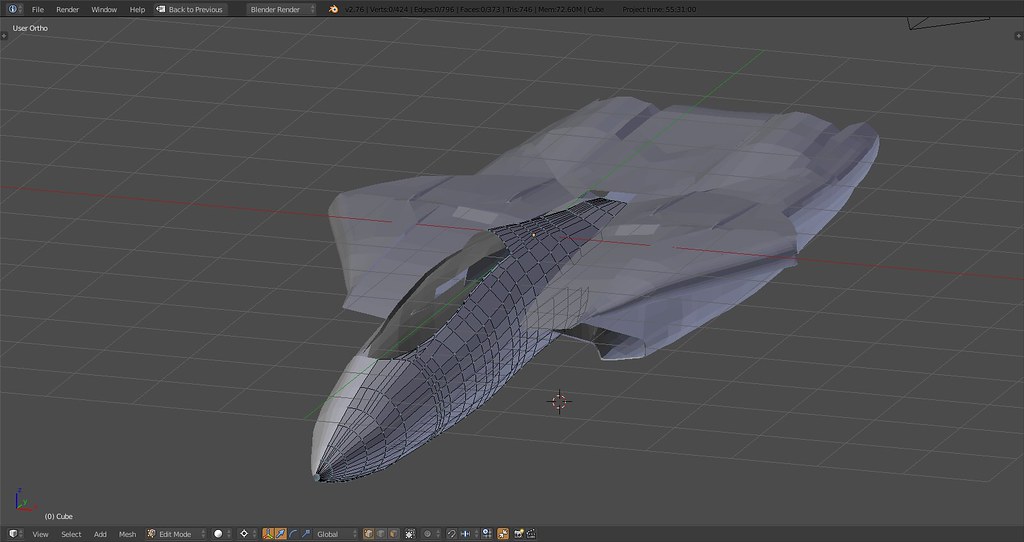
pods mated to glove box, engine shrouds and lower intake frame up next…
-
Finally an F-14 model that we can use! Thanks Stingray, it looks great, you don’t need any help, but if you need anything let me know. Awesome job.
-
The “Chairman of the Board” is pleased!


-
Well said my friend……!!! :headb:
-
I can’t wait to danger zone it up…
")
-
Yeah I hope a release before 2017 for kill these damned MiG-28 ! Haha !

-
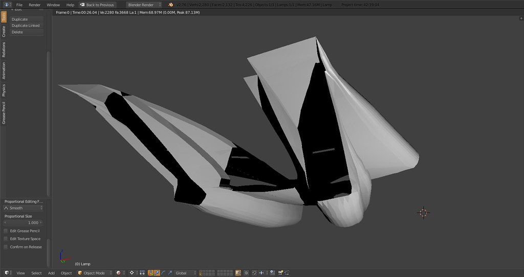
added some depth to the intakes and finalized the lower intake shape, also added topside stabilizers
-
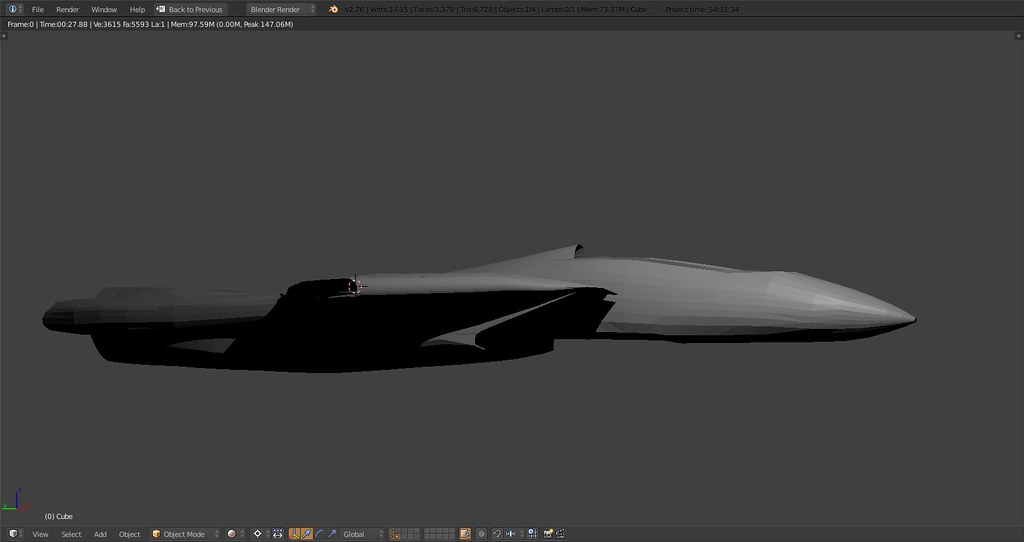
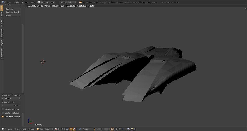
and with corrected windshield area:
and a little playing around with horizontal stabs and droptanks:
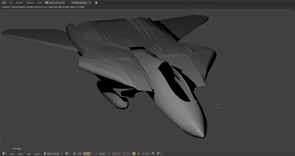
turned out that the engine shroud and housing on the upper reardeck cannot be correctly modelled without the front top fuselage so I’m finalizing and attaching that before moving on to the rear deck
-
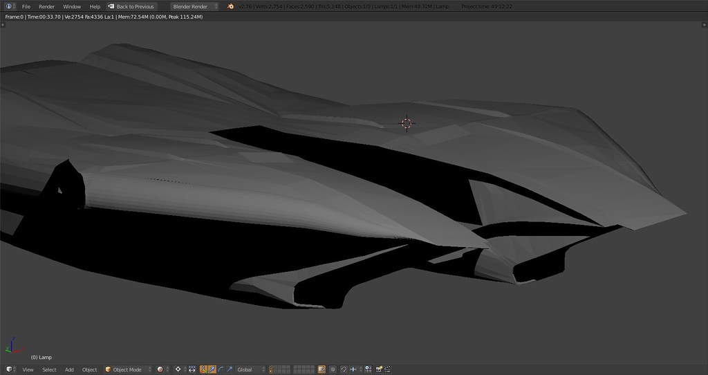
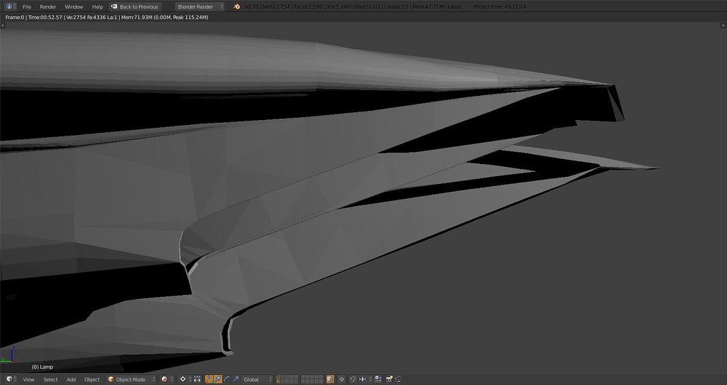
I have a question some of you might be able to help me with. It’s about the following areas:
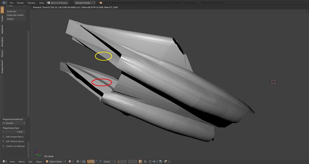
Yellow is the inside of the intake and the side of these faces that should be textured while red is the backside of the same face area. I have flipped the faces so the inside of the intake is ‘up’.
I’m wondering if I should do anything more with these faces in terms of assigning or flipping them now or is that sth I can deal with in 3ds later on?
I’d like to take care of that before modeling anymore of the intake/compressor part of the engines.
-
I think I’d try to model and texture both sides of the inner intake wall. The one that’s barely visible maybe just with lower detail. The BMS engine probably uses the vertex normals for lighting calculations so if you have an area flipped the opposite way it might look strange when it comes to lighting. Or am I not understanding?
-
Thanks zimluura.
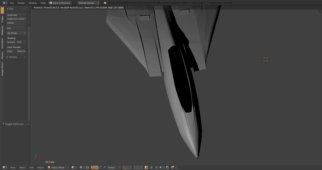
Re your understanding: sorta:) …it’s not visible at all. It’s simply the backside of the inner intake. Specifically I’m talking about the upper right part of the red circle. So not the lower left which would be as you say barely visible as it’s positioned between fuselage and intake but the part 'in’side the A/C.
I don’t think I’ve flipped it the opposite way it’s just assigning which side of a face is ‘up’. I guess when it comes to something having a back- and a frontside I’d just bevel the face thereby creating front and back.
-
Sorta…it’s not visible at all. It’s simply the backside of the inner intake. Won’t ever be textured or anything…
Then don’t model it.
")
… you’ll have a hard time to keep tri - count inside BMS specs anyway.
Cheers,

LS -
My rough calculations have me come out at roughly 22.000 for the fuselage, glovebox, stabs and details leaving 8.000 for the wings. Even 20 and 5 would be fine in my estimate. WaveyDave said his Tornado at 30K tris should be a upper limit in terms of desired spec so that should work.
But yeah - I’ll have a hard time anyway :D.
About the modeling, I don’t wanna model anything that will be invisible but the face’s backside is there - I’m just wondering is this a question of mapping and texture assignment or do I manipulate sth beyond that?!
-
My rough calculations have me come out at roughly 22.000 for the fuselage, glovebox, stabs and details leaving 8.000 for the wings. Even 20 and 5 would be fine in my estimate. WaveyDave said his Tornado at 30K tris should be a upper limit in terms of desired spec so that should work.
Don’t forget gear in your calculation. They can take up a lot of polys.
-
Funny you should mention that, I was thinking about it when I wrote that then I figured it must be excluded from the 30k.
 gotta love a good challenge
 -
I think I see now. I’d remove anything that will never be visible*. Typically (from non-BMS modeling), I’ll delete the faces leading up to the intersection, then select two edges and pres F to create a new face spanning the gap. Though I guess this approach might make it more difficult to add in extra detail later with a curvy surface and a flat(ish) one that isn’t on a perfect YZ plane.
-
I think I see now. I’d remove anything that will never be visible*. Typically (from non-BMS modeling), I’ll delete the faces leading up to the intersection, then select two edges and pres F to create a new face spanning the gap. Though I guess this approach might make it more difficult to add in extra detail later with a curvy surface and a flat(ish) one that isn’t on a perfect YZ plane.
‘the face spanning the gap’ is the one you see in my picture. It is a perfect xy plane and it is on the inside of the intake. The backside of that face is what you see inside the ‘triangle’ between the upper outside part of the top intake and the lower outside part of the fuselage finish. I’ll mark it tomo to make it clear. I guess it shouldn’t be a problem for now.
Thanks for the input man!