WIP: F-14 B/D
-
F-14 Pilot : “Phoenix, Phoenix, whatcha gonna do, whatcha gonna do when they come for you !”
MiG Pilot : “Holy shit…”:wfish:
As it Stands, with the current Ingame F-14 I’ve actually scored kills on Two MiG-21s at a launch range of 65 and 43 Nautical Miles.

-
As it Stands, with the current Ingame F-14 I’ve actually scored kills on Two MiG-21s at a launch range of 65 and 43 Nautical Miles.
Sweeeet :). You using Molni’s launch profile for the Phoenix?
-
I wasn’t aware there was one. Went 10 degrees Nose Up at 28k and fired.
-
I wasn’t aware there was one. Went 10 degrees Nose Up at 28k and fired.
It’s just a tweak for launch and flight path…
Just to clarify this is just concerning the AIM-54 not the F-14 avionics or weapons systems (as far as you can call them that). That being said the way you described works quite good and is pretty close to RL though some say the current FM/AFM is overpowered somewhat. I’d say true in some parts of the envelope absolutely not true in others but that’s another story.
-
It might have been mentioned before, so please forgive me if this is a double post, but it’s too good to miss on IMHO
Aside from the usual bravado, we get some very interesting insights into the Tomcat’s design and capabilities.
All the best,
Uwe
System specs: win10pro / Linux Mint 21.x, 32GB RAM, RTX3070, 2x1 TB SSD, 1x2TB NVMe, 1x4TB SATA; HOTAS Warthog Stick(DX), WinWing Orion2 Throttle w/ f16 grip, TM MFDs, CH Pro Flight Pedals w/ custom USB controller; CPU: AMD Ryzen 7 3700X 8-Core; MoBo: X570-A PRO (MS-7C37); Display: 42" LG Nano 42 (2560x1440), 19" Fujitsu-Siemens (1280x1024) used for DE /w YAME64 beta; DelanClip /w PS Eye, opentrack; GameTrix JetSeat /w SimShaker Wings; Stream Deck XL (32 buttons) as ICP
-
For pure design and tech discussion from an insider in presentation form I can recommend this:
At 16:02 the man goes into the canvass airbag and the overwing fairing with titanium fingers which ‘clamp’ into the airbag creating almost a near seamless contour.
When modeling I never understood what those three ‘fingers’ are until I heard him explain it. This lecture is priceless for any Tomcatter and aviation enthusiast in general.
It might have been mentioned before, so please forgive me if this is a double post, but it’s too good to miss on IMHO
Aside from the usual bravado, we get some very interesting insights into the Tomcat’s design and capabilities.
All the best,
Uwe
-
Interesting movie. Thk’s

-
Yeap really nice. Nice looking airframe with fine features at the time. If it had a better engine from the beginning…
Sent from TapaTalk
HOT LIST

System Specs:
i7-2600K @ 4.8 Ghz WaterCooled / 32GB Ram. 128GB SSD/1TB SSD / GTX1080Ti 11GB DDR5X / HOTAS COUGAR. TrackIR 4 / 3x24" Mon. (res:5760x1200) / Cougar MFD's / Wheel Pedals / Win 10 64 bit.

-
Alright guys, small update on the landing gear rigging process. As stated before this is necessary to finish hard surface modelling and ensure scale, fit and proportion.
The following is very dry, will be boring to most and there are no fancy animations yet BUT to a tiny minority it might be quite interesting :).
After trying with empties as constraints and some other ‘non-bone’ rigging I decided that I need an armature and bones rigging to make it work.
For anyone who doesn’t know what this is, basically you use rigging techniques designed for organic, deforming objects (like a human hand) and apply it to non-deforming mechanical assemblies.
Current status:

What you see is main strut actuator piston that rotates the entire MLG on top left, main strut piston on lower left, support beam rig on the lower right. I’ll go through this in the following. The structure is always a bone with tip and base and a control bone that determines the position of the tip and thereby extends/retracts a piston.

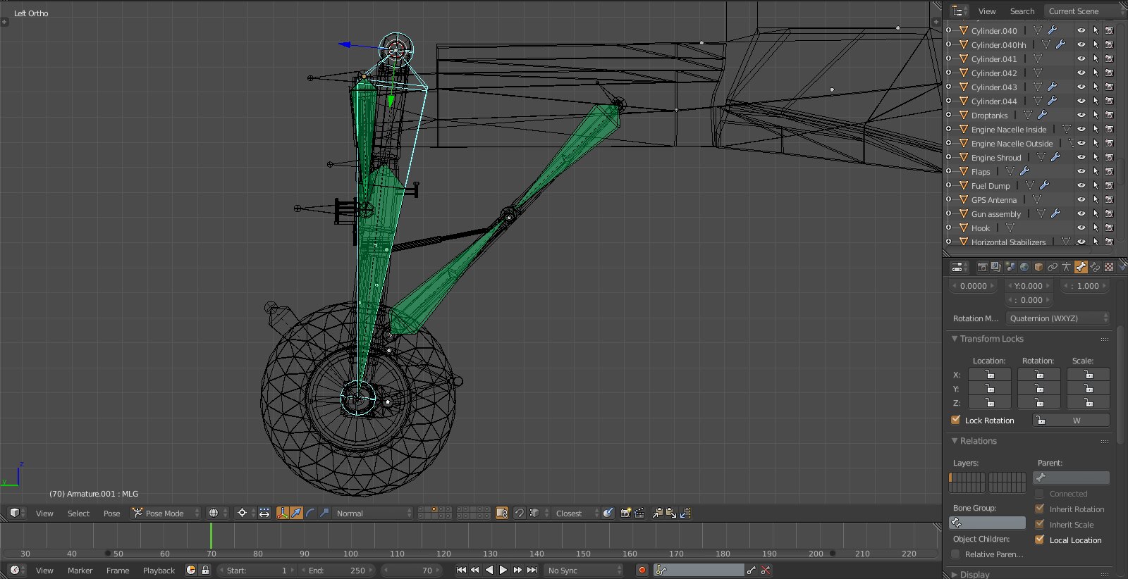
Note the control of the main strut actuator rotated to the ‘retracted’ position and the actuator bone extended. This rig will connect to vertex groups and result in the piston extending out of the base as would be the case in RL.

Working on the main strut, you can see the tip which will attach to the wheelhub part extend. Haven’t decided on where it makes most sense to attach the control bone as it simply extends out and down on the local Z axis.

Now this is something special. Simple stuff is the piston that operates the lower part of the support beam retracting. Now you have the upper part of the support beam extending which it shouldn’t do as it is a solid object.
Thing to remember is the two parts have the same length. Blender allows you to assign objects also to the control bone. So I’ll assign the lower part of the support beam to the control bone which is solid and simply rotates and then compensate the extension of the upper part by rotating the entire assembly up thereby keeping the length of the upper beam constant.
It’ll be evident once I have the animation done.
Now I ‘just’ have to finish the armature in terms of parenting it accordingly and then AND THEN have the lower part of the strut (where support beams, wheel and lower scissors as well as blocking T are attached) rotate inward as the assembly rotates upward.
Fear the Bones, Baby. - pun intended
-
Pete,
you are aware that you’ll need to do the animation in 3dsmax
with DOFs?Your bones might be only helpfull there to align the DOFs in
position and direction.… just saying before you cry about wasted time again.
")
Sent from my laptop using keyboard.
Cheers,

LSmy Rig:
Alienware "Aurora" I7-960 3,2 GHz / 18 GB DDR3 / GeForce 1070 GTX 8GB /
1x500 GB SSD / 1x2 TB SATA II (1x1,5 TB SATA II for backup)
Hotas Cougar Nr.:16387 / FCC-3 / Elite Rudder pedals / TrackIR4 / Win10 x64 Home -
Pete,
you are aware that you’ll need to do the animation in 3dsmax
with DOFs?Yes, read my post again and it will become obvious. Am I aware of what exactly to do in 3ds and how it all works and how the DOFs and animation and implementation works? Not at all!
Your bones might be only helpfull there to align the DOFs in
position and direction.Again - this is about finishing hard surface modelling in Blender, understanding the rigging process and learning how the parts play together. As far as bones being helpful you bet your ass they are :).
… just saying before you cry about wasted time again.
I don’t think I’m in the habit of crying about wasted time and I doubt I’ve ever done it before so I don’t plan on doing it ‘again’ :D.
-
Alright guys, small update on the landing gear rigging process. As stated before this is necessary to finish hard surface modelling and ensure scale, fit and proportion.
The following is very dry, will be boring to most and there are no fancy animations yet BUT to a tiny minority it might be quite interesting :).
After trying with empties as constraints and some other ‘non-bone’ rigging I decided that I need an armature and bones rigging to make it work.
For anyone who doesn’t know what this is, basically you use rigging techniques designed for organic, deforming objects (like a human hand) and apply it to non-deforming mechanical assemblies.
Current status:
https://c7.staticflickr.com/6/5738/30117505262_f8a1f062c3_h.jpg
What you see is main strut actuator piston that rotates the entire MLG on top left, main strut piston on lower left, support beam rig on the lower right. I’ll go through this in the following. The structure is always a bone with tip and base and a control bone that determines the position of the tip and thereby extends/retracts a piston.
https://c1.staticflickr.com/9/8130/30117505232_9742e2060c_h.jpg
Note the control of the main strut actuator rotated to the ‘retracted’ position and the actuator bone extended. This rig will connect to vertex groups and result in the piston extending out of the base as would be the case in RL.
https://c5.staticflickr.com/9/8644/30117505172_4066fd660a_h.jpg
Working on the main strut, you can see the tip which will attach to the wheelhub part extend. Haven’t decided on where it makes most sense to attach the control bone as it simply extends out and down on the local Z axis.
https://c3.staticflickr.com/9/8133/30117505362_2e5cc7378b_h.jpg
Now this is something special. Simple stuff is the piston that operates the lower part of the support beam retracting. Now you have the upper part of the support beam extending which it shouldn’t do as it is a solid object.
Thing to remember is the two parts have the same length. Blender allows you to assign objects also to the control bone. So I’ll assign the lower part of the support beam to the control bone which is solid and simply rotates and then compensate the extension of the upper part by rotating the entire assembly up thereby keeping the length of the upper beam constant.
It’ll be evident once I have the animation done.
Now I ‘just’ have to finish the armature in terms of parenting it accordingly and then AND THEN have the lower part of the strut (where support beams, wheel and lower scissors as well as blocking T are attached) rotate inward as the assembly rotates upward.
Fear the Bones, Baby. - pun intended
Hm interesting technique…. Im new in this also it might help me in the phantom i porting… i never thought of it! I will try it! I tried empties and points but i didnt understand it too much. So the dofs i asume are going in to the bones? By the way i found easier to work in 3ds rather in blender. dont ask my why… maybe is the way mouse works in blender…
Tοις τολμώσιν η τύχη ξύμφορός εστιν (Luck helps those who dare - Thucydides)

-
It’s just a tweak for launch and flight path…
Just to clarify this is just concerning the AIM-54 not the F-14 avionics or weapons systems (as far as you can call them that). That being said the way you described works quite good and is pretty close to RL though some say the current FM/AFM is overpowered somewhat. I’d say true in some parts of the envelope absolutely not true in others but that’s another story.
Since 4.33 all AAM has drop method - which looks weird on F-16 - as I know. I made this MOD by altering thrust values in dat file.
-
Hm interesting technique…. Im new in this also it might help me in the phantom i porting… i never thought of it! I will try it! I tried empties and points but i didnt understand it too much. So the dofs i asume are going in to the bones? By the way i found easier to work in 3ds rather in blender. dont ask my why… maybe is the way mouse works in blender…
I just couldn’t get it to work with empties and points and since it is irrelevant how I get it to work in Blender as I just need the fastest and most accurate way to animate it I went with the armature.
WaveyDave or PumpyHead have commented in this thread before how the landing gear can be done with a couple of rotation and transformation DOFs in 3ds and I’ll look into that once the model is ready. I guess the logic behind it will be the same as in assigning the vertex groups, setting constraints and setting the rotation angle.
Not sure if there even are bones when you do it with the DOFs using WaveyDave’s exporter…
Interestingly (I think) I can use the data from my armature rig in Blender for the DOFs in 3ds, it will provide precise locations, degrees of rotation and order of animation so that should help.
-
Since 4.33 all AAM has drop method - which looks weird on F-16 - as I know. I made this MOD by altering thrust values in dat file.
Well, in 4.33.0 the missile were indeed dropped way too much. This was fixed in U1.
Now, the missile still drops a bit, but that is to be expected since we dont really have rail force modeling - the missile doesnt “slide” on its rail, it just is “released”. The illusion is good enough since thrust happens almost instantly and push the missile forward.
But then you have to contend with missiles like the AIM-120 or AIM-7, that can be either on a rail or dropped (pushed, really) from underbelly stations. At which point you have to compromise on the thrust profile : either it happens right away, in which case it looks good on rails but weird on underbelly (the missile basically looks like it scratches the belly) - or you delay the thrust, in which case it looks ok on underbelly but weird on rails, since the missile will drop.
Fortunately, with the Phoenix it is always dropped, so no compromise to make
.") I made a 0.5s delay for ignition, which is quite true to the
I made a 0.5s delay for ignition, which is quite true to the -
I don’t think I’m in the habit of crying about wasted time and I doubt I’ve ever done it before so I don’t plan on doing it ‘again’ :D.
I was just thinking about post #377:
@stingray_SIX_TWO:Shit man I wanna cry, that would’ve saved me like 300 hours :D.
Haha…on it goes.Sent from my laptop using keyboard.
Cheers,
LS -
That wasn’t crying man that’s telling it how it is. I loved every one of those 300hrs lemme tell ya
On that issue I was thinking is there actually any instance in which it makes sense to have objects/bodies connected into one mesh (for instance the vertical stabs which I painstakingly integrated into the topside of the fuselage) or is that totally unnecessary?
-
Fortunately, with the Phoenix it is always dropped, so no compromise to make
. I made a 0.5s delay for ignition, which is quite true to the Awesome! Thanks for the info.
-
And I ran into the first problem, the kind I was hoping to bring out with the bones exercise. As you can see the support beam geometry is off. They’re supposed to fold like a scissor and then jointly move up with the landing gear.
The upper part is attached to the fuselage in RL and is fixed here as well (at the base), both parts are locked in size and cannot deform and they track each other. In and of itself this system works perfectly.


Through parenting the MLG moves up and the main actuator extends as it should, the lower beam folds toward the MLG and the upper beam tracks it BUT as it moves up the folding stops to work because
a) location of fuselage pivot point of MLG or beam or both is/are wrong
b) the beams have the wrong size
c) all of the aboveBack to the drawing board :). I might play with the bones until I have a setup that works and then modify the objects accordingly or really just do a tech drawing and calculate the positions and use that as a basis. The blueprints don’t help here.
-
Well if it folds in as it should and doesn’t show externally, it’s not a problem. Like who cares if it fits in or not.
Also those movements u will have to redo in 3dsMAX to set the dofs correctly. Sure having the model in correct order and measures will make it easier but just saying it might be double work, where only the last is needed actually.
Sent from TapaTalk
HOT LIST
System Specs:
i7-2600K @ 4.8 Ghz WaterCooled / 32GB Ram. 128GB SSD/1TB SSD / GTX1080Ti 11GB DDR5X / HOTAS COUGAR. TrackIR 4 / 3x24" Mon. (res:5760x1200) / Cougar MFD's / Wheel Pedals / Win 10 64 bit.