Airport Construction Guide for Falcon BMS 4.33+ by Cannon
-
Hmmm accidentally we may discovered something that could be used on purpose…
I have training mostly on my mind like surpriiiiiise… act quickly or die.
I’m not talking about regular missions.Thanx for verification glad I could help.
Sent from TapaTalk
HOT LIST

System Specs:
i7-2600K @ 4.8 Ghz WaterCooled / 32GB Ram. 128GB SSD/1TB SSD / GTX1080Ti 11GB DDR5X / HOTAS COUGAR. TrackIR 4 / 3x24" Mon. (res:5760x1200) / Cougar MFD's / Wheel Pedals / Win 10 64 bit.

-
Right on!!
For other airbase developers, just increase last LOD distance for the runways and taxiways for 10.000.000.
Many thanks
-
Hello everyone,
I just started modelling Seosan Airbase. I need to say that I am a newbie at modelling. I am doing this to learn how to model an airport because I am probably obsessed with realistic airports:). But I need help. So decided wake up this thread. I am using cannon’s guide and It is great. But there is a point that I am stuck. That point is painting the skin. I have never painted a skin in my life before although I modelled some stuff before. I found information about painting the skin on the internet but I got quite confused. So I will be very If someone explains painting the airport skin properly I would be very happy. And do not forget that I am a newbie. I thought this would also help to other people like me. Thanks in advance for your answers.
-
There isn’t just one rule or way.
U have 2 - 3 sections to consider.
1. Basic material
2. Markings
3. WeatheringU can work on the texture directly but working piece by piece u will face the problem to allign lines and markings.
For the markings u should use paths in Photoshop, or AutoCAD, or Corel draw and vectors.
In Corel u can scale things down so that the whole airbase can fit in one file.If you do it with photos and Photoshop and you want ultra resolution then you will need a monster PC to work on a single file as a whole airport and then cut it to pieces.
The weathering now makes the overkill. U must apply it to both, base material and markings.
Like tyremarks, paint scratches on the edges of markings and dirt.Now instead of going on a solo file for the whole airport you could breaker it to pieces. So one piece to work on it and have next previous pieces so to allign things correctly with pixel precision. I’ve done that when I was doing the HD runways project.
Another approach would be PBR like substance painter. But you will need also substance designer. With designer you can create the library for specific markings to fit perfectly and correctly on your model. Also in painter a whole airbase will need a strong PC.
With PBR u can make all the markings 3d. Then apply the materials and get a superb result.
I know very general post but going in details will need many pages.
Also to clear it out I’m not an expert, just a bit experienced and old.
Στάλθηκε από το MI 5 μου χρησιμοποιώντας Tapatalk
HOT LIST
System Specs:
i7-2600K @ 4.8 Ghz WaterCooled / 32GB Ram. 128GB SSD/1TB SSD / GTX1080Ti 11GB DDR5X / HOTAS COUGAR. TrackIR 4 / 3x24" Mon. (res:5760x1200) / Cougar MFD's / Wheel Pedals / Win 10 64 bit.
-
This is an extremely ignorant suggestion, but for vector art I use Inkscape:
Inkscape can export a lossless vector file in .svg or .dxf format, or a .png raster file at any resolution you want. Last time I checked, Adobe products didn’t like .svg… probably because Adobe didn’t come up with it. BUT, this might be a nice alternative to programs which, if properly acquired, cost boatloads of cash. Inkscape is free!
-
What size is the max that inkspace can handle?
Can I make a 1km vector line for instance?Στάλθηκε από το MI 5 μου χρησιμοποιώντας Tapatalk
HOT LIST
System Specs:
i7-2600K @ 4.8 Ghz WaterCooled / 32GB Ram. 128GB SSD/1TB SSD / GTX1080Ti 11GB DDR5X / HOTAS COUGAR. TrackIR 4 / 3x24" Mon. (res:5760x1200) / Cougar MFD's / Wheel Pedals / Win 10 64 bit.
-
I don’t see why you couldn’t. You’d just get rid of any pre-set boarder and use a completely blank canvass. Vector files basically have no resolution: you can scale them to any size. This means you could also work at sub-scale, or greater, etc.
On the other hand, you clearly know what you’re doing with the software you already have. Asking you to learn a new program, with its own frustrations and limitations would be kind of foolish. You learn software you either want to use or have to use. To be honest, I wish more programs offered the precision and control of AutoCAD, without necessarily being AutoCAD. It’s kind of why I like AC3D as a modeling program - I can be very precise. All the while, you can see the work of the Blender artists speak for itself… I haven’t managed to stomach learning blender, so I stick with the program I started with.
So, comparing Inkscape to AutoCAD, it’s kind of like AC3D to AutoCAD: I can be very precise, but that precision comes from manual control of EVERYTHING. But, the program is free and accessible, and …should… export file formats that would be useful to modders.
Also note that rastering functions are generally not a strong point in vector art programs, so you might need GIMP or Adobe for some of the things you mentioned in your post above my first.
-
Hi mhm.
I will give you my opinion based on what I know and what I have seen other do and found clever.
I will also give a brief scheme of a line of work to create an airbase from scratch:
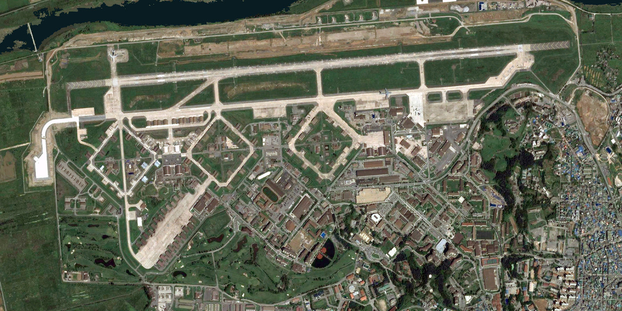
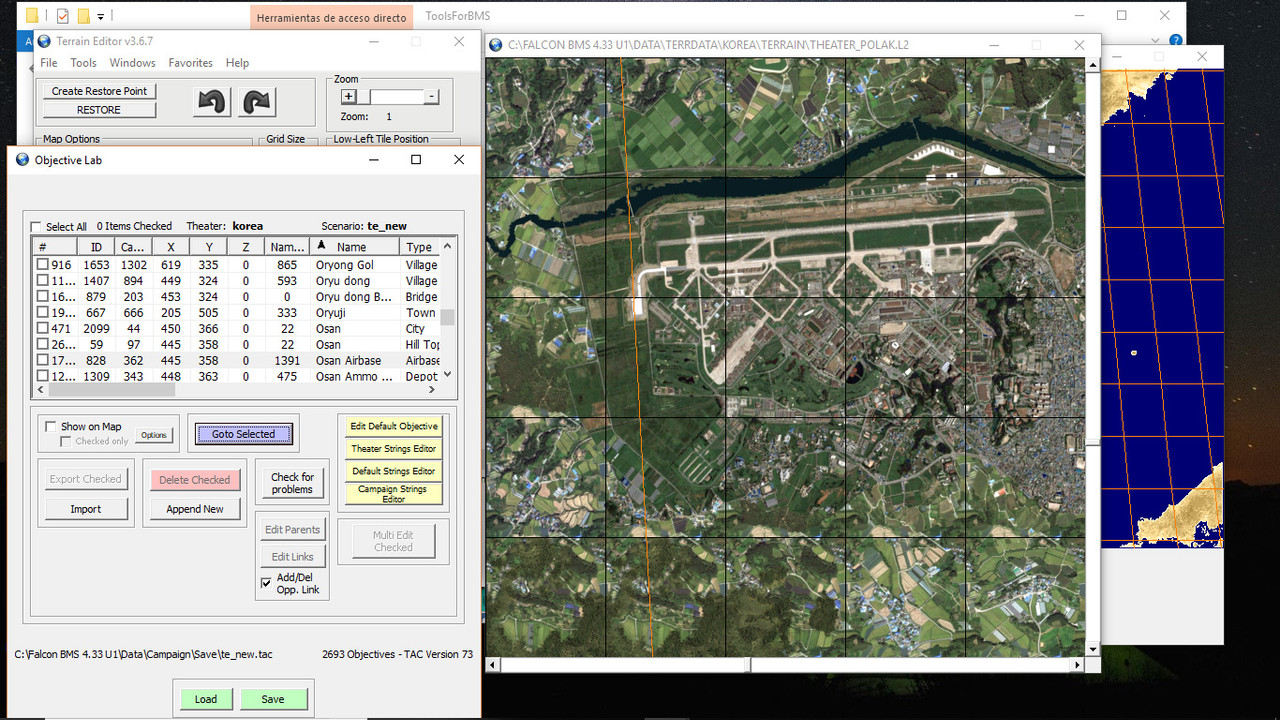
- Get reference images of what you need. Either the already existing textures in the theater (if they are photorealistic) or use a software to capture Satellite images. i.e. SASPlanet…
This image is taken from TerrainEditor, one tile at a time, then all have been composed together using photoshop:
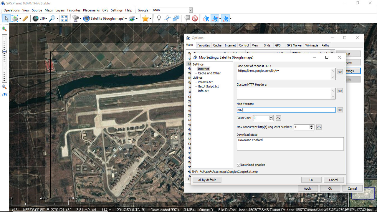
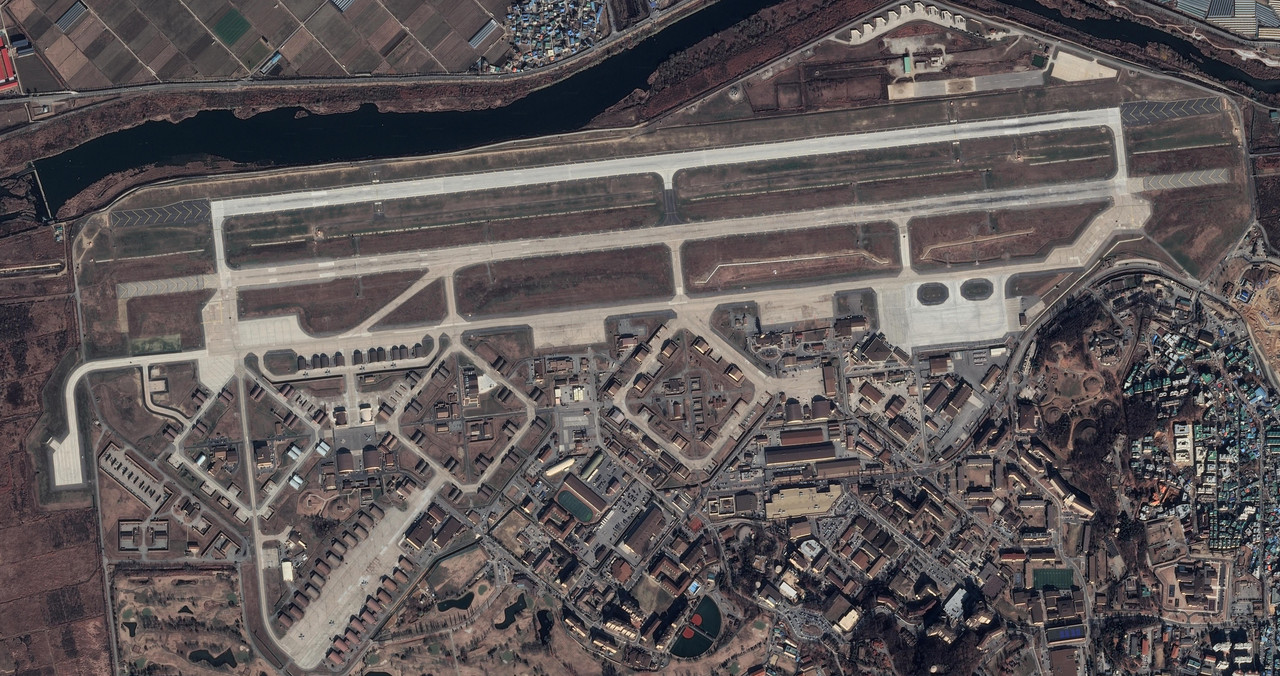
With SASPlanet you can get better resolution and chose from different sources: Bing, Google…
But you need to update the version of google maps under its setting in sasplanet, to get the images of google working. You can find the version by looking at the source code of google maps website:
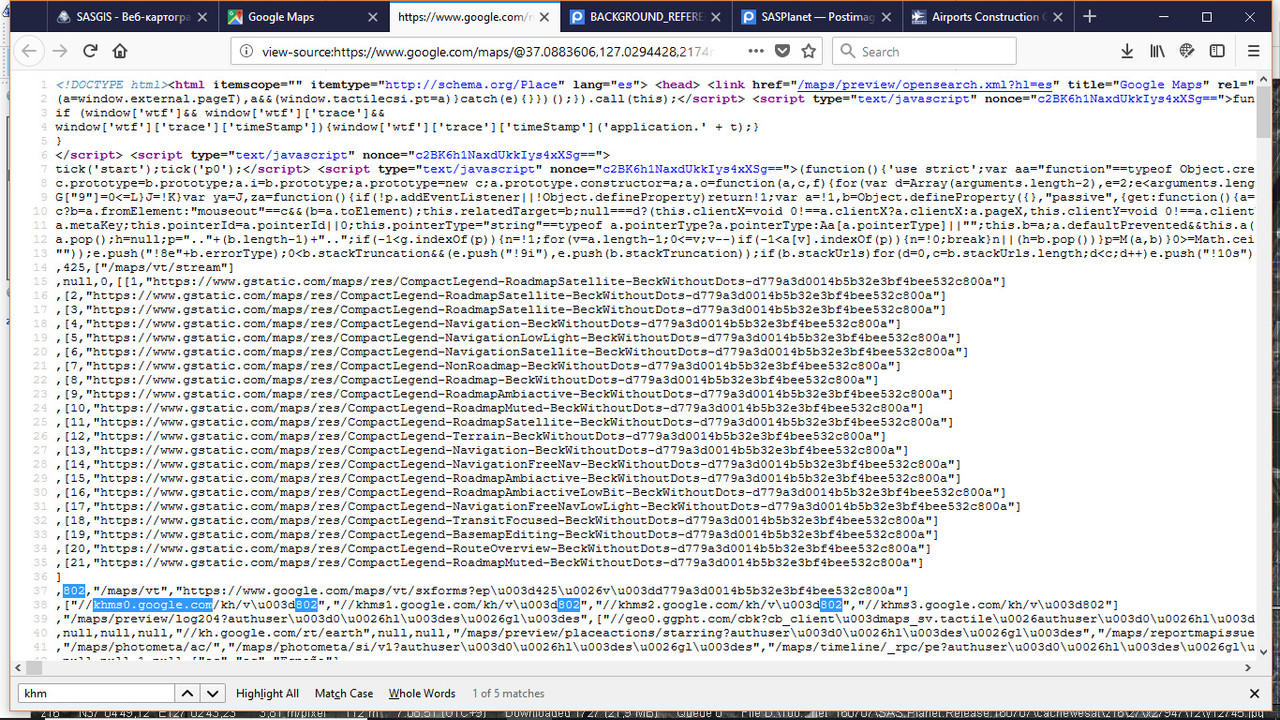
This image was obtained using the “stich” option of sasplanet in zoom level 19:
Once you have good reference for both buiding on top and for a source in textures you are ready to go.
I made a mistake on 14’00’’ and beyond. You need to measure the rectangular selection. The stitch function in SASPLanet does trim the image to the selection. Sorry about the confusion.- Prepare the database -this could be done afterwards modeling, but it would be a pity to do the 3d job without understanding this, because you could be doing the work wrongly- (THis needs you to understand the database. What is an objective, whats a feature, the different kinds, etc): (a)If what you want to do is replace every feature that is already existing inside the Objective (i.e. OSAN objective) No need to do anything, but replace the LODs with the new ones in the 3d database. (LODEditor… or else). (b)If you are going to build a totally new objective, or totally new features within an existing objective you would need to create new “entries” in the database by cloning existing ones that match characteristics with the ones you want to introduce:(tracks, lights, buildings, etc etc…)
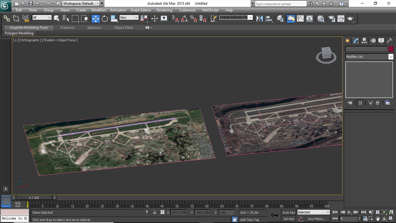
3)Start modelling on top of your reference images using directly 3dSMax. THere are similar tools in max that can save you the hustle to go forth and back from Illustrator (Thats what i used as vector software) Inskpace or whatever. Know how to use vector tools in 3dsmax and save time. IMHO.
4)While modelling all your features in one single max file, you learn how to “Bake” all your different materials into one single texture for all normal looking material (ptype9), and if you use alphas (transparency) bake those separatedly.
- DOn’t forget the LOD2,3,4 and DAMAGED and DESTROYED versions of each feature,
6)Export everything into LOD. format.
7)Open your created textures with image edit software to add fx like burnt tires etc.
-
Replace lods and textures , or insert new ones in the 3d database and texture folders.
-
Fly, notice errors and correct.
I know is of not much help for specificly “Skinning” but to give you an overview of a way to do this.
If I can I will try to be more specific about skinning later on.
EDIT: Check this post where I also deal with this issue–-> https://www.benchmarksims.org/forum/showthread.php?33986-Airports-Airbase-construction-videos
-
Thanks for the answers guys. I just realized I have made some mistakes during the beginning. I believe I fixed them. I building Seosan from scratch. But still, need lots of advice:)
-
For runways taxiway u must split the object to smaller pieces like 5 and for sure the crossing areas. This is cause when bombed they must be replaced with the damaged or destroyed models.
For the markings u might need some math.
Meaning how wide is the taxiline? 20cm? How many pixels it must be in my models texture?
How detailed and not pixelated you want it?
Have in mind that something good looking in Photoshop will not look that great when it will become dds cause of the compression. So minimum for the Taxiway would be the 2048^2 depending and how you map the model texture.
8192^2 for good details and maybe 4096^2 for not so detailed areas. Have in mind the streching… Like same cement area one at 8192 the other in 4096 if they are not scaled correctly might look ugly at the point they connect together.Στάλθηκε από το MI 5 μου χρησιμοποιώντας Tapatalk
HOT LIST
System Specs:
i7-2600K @ 4.8 Ghz WaterCooled / 32GB Ram. 128GB SSD/1TB SSD / GTX1080Ti 11GB DDR5X / HOTAS COUGAR. TrackIR 4 / 3x24" Mon. (res:5760x1200) / Cougar MFD's / Wheel Pedals / Win 10 64 bit.
-
Hello everyone,
I believe I am making some progress but this time I have another issue. I am stuck at the section 8C of the cannon’s guide. When I try to model check I cannot convert all airport model to editable poly. This is what happens:
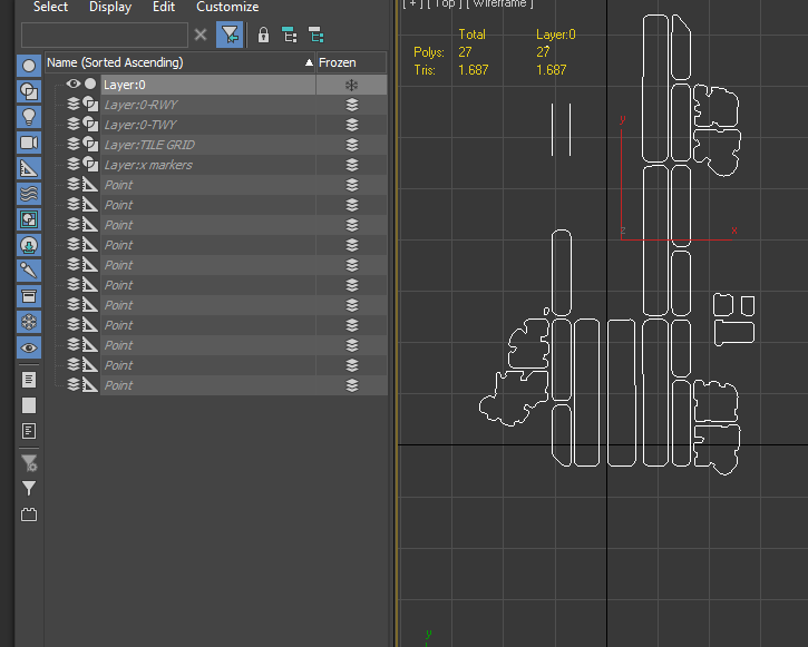
I believe there might be a problem about layers. But it also might be about welding process. When I try to weld it says(for example) “566 vertices out of 1641 welded”. So I think 3dsmax cannot process all the vertices. I do not why is this happening.
-
As I see u don’t have one object but many. 25 if I counted correctly.
u don’t select all the objects at once and then weld and then convert to editable poly. do it one by one.
select one weld it then right click convert to editable poly. then move to the next.
Alternatively on each object weld it and add an edit poly modifier.Edit:
If you work on 3dsmax 2017 u have an issue as iirc you can’t go back to 2013 or 2014 to be able to export it.on that guide if u export as it says and import to falcon you will have a perfect aligned airbase as you see it in the 3dsmax.
BUT
when you go to target assignment and recon page you will discover the issue.
every part of the runway that you select the view will be on the center of the runway and not on the center of the part you want.To achieve such you must center first the center of the part in 3dsmax x=0 y=0 and then export it.
This means that you will have to reassemble the airbase parts in Falcon Editor which is a great pain.
but when you go to recon and select one part it will center the view to the part you selected.example if u have a rwy and is of 5 parts 12345 logically your whole model will be centered very close to part3.
If u export as the guide says when you go to recon and select part1 the view will display the center of part3. whatever part you select you will see part3 always.Lets hope that the new tool that Mortesil is preparing will solve this issue and make objects placement an ease and as is in 3ds max.
-
Thanks for the reply Arty. Yes, I am using 3ds Max 2017. This time I get “no vertices within weld threshold” error. I tried to change welding setting(the values) but it did not help. Also, haven’t find a solution on the internet:(.
-
Then it’s welded. The message you get it’s not an error it’s informative.
To check, select one object then go to vertices pick one from the object and move it. If you see the line breaking then it’s not welded. To select one vertice point and click to select, do not drag select, that way you will select only one vertice.Στάλθηκε από το MI 5 μου χρησιμοποιώντας Tapatalk
HOT LIST
System Specs:
i7-2600K @ 4.8 Ghz WaterCooled / 32GB Ram. 128GB SSD/1TB SSD / GTX1080Ti 11GB DDR5X / HOTAS COUGAR. TrackIR 4 / 3x24" Mon. (res:5760x1200) / Cougar MFD's / Wheel Pedals / Win 10 64 bit.
-
I have edited my previous post to expand the info. I intend in doing so more.
If you work on 3dsmax 2017 u have an issue as iirc you can’t go back to 2013 or 2014 to be able to export it.
on that guide if u export as it says and import to falcon you will have a perfect aligned airbase as you see it in the 3dsmax.
BUT
when you go to target assignment and recon page you will discover the issue.
every part of the runway that you select the view will be on the center of the runway and not on the center of the part you want.To achieve such you must center first the center of the part in 3dsmax x=0 y=0 and then export it.
This means that you will have to reassemble the airbase parts in Falcon Editor which is a great pain.
but when you go to recon and select one part it will center the view to the part you selected.You will need a 3dsMax version that can use the exporter plugin. 2012 or 2013 IIRC.
Also, what Arty says is an issue. My advice is, once you have everything done in one max file export each feature to a different file in 3dsMax and there center your object to x:0, y:0 then you export your feature into .LOD from this file.
-
@mhm:
Thanks for the reply Arty. Yes, I am using 3ds Max 2017. This time I get “no vertices within weld threshold” error. I tried to change welding setting(the values) but it did not help. Also, haven’t find a solution on the internet:(.
I solved this issue. This was a 3ds Max issue. I extruded the splines than converted to editable poly successfully. Also still having an issue with painting the skin and vector graphics. Currently looking at some educational videos.
I saw your edit BlackWolf. Thank you so much. I will keep this post updated.
-
Did you close the spline? This is critical to convert correctly a spline into editable poly
Enviado desde mi Aquaris V mediante Tapatalk
-
extrude? I wouldn’t say that this is a good practice.
if the spline is closed and not coming from autocad , meaning you created it in 3dsmax then just select it and convert it to editable poly.
Also before you continue set your measurements correctly. like meters and details level.
1. Customize->units setup. ( I use meters always)
2. Customize->units setup->System unit setup. (I use meter also)Then start modeling.
What issue do you have with painting it?
First u must uvw unwrap the model. This a whole chapter.
Recently Radium pointed to me those guides:then the mapping must be exported to png for example.
this png mapping will be your guideline to paint the parts of the model.
This can go to photoshop or whatever app you like and there paint it. convert it to dds format (mostly done with photoshop)
come back and in 3ds max and apply the material with the skin to the object.
dds names must be numbers a number that isn;t used already by falcon. To look for them look at
C:\Falcon BMS 4.33 U1\Data\Terrdata\objects\KoreaObj\if you don’t want to use a skin - picture but a basic color then when you select a material declare the color in the difuse then apply the material to the model.
This color will be displayed in falcon and you don’t need a dds texture. we usually do this to test the basics of the model or for a quick look in falcon 3d.HOT LIST
System Specs:
i7-2600K @ 4.8 Ghz WaterCooled / 32GB Ram. 128GB SSD/1TB SSD / GTX1080Ti 11GB DDR5X / HOTAS COUGAR. TrackIR 4 / 3x24" Mon. (res:5760x1200) / Cougar MFD's / Wheel Pedals / Win 10 64 bit.
-
Actually, I asked someone in AutoDesk 3ds Max forum, he told me to use extrude command. Also, I completed painting, but I did not understand how I managed to do that:). Like Arty said just for test purposes I am going without skin for now. I am watching educational videos right now. I think I need to settle the idea behind the idea of those commands. Again thank you guys.
-
Mhm good to ask around and try to find solutions by your self.
The thing is sometimes things have some rules in modeling but when it comes to falcon there are specifications that might cause issues.
Example:
If u create a rwy part as spline first cause you import it from AutoCAD.
If u make it a poly in 3dsmax it could be 2tris.
If u extrude it lets say only one centimeter it will get 10tris minimum.
If you import it in falcon and don’t have in mind this extrusion when you use it in BMS the airplane could collide and explode the aircraft.
This 1cm will produce shadows. Shadows are fps eaters.Also have in mind that the fact that a guy responded something in AutoCAD or 3ds forum doesn’t mean he is knowledgeable.
I’m not saying that those guys ain’t but also depends on the question you put.I have seen many tutorials many forums many guides… If I applied what I learned for falcon it would be a killer for fps.
I can create and export a city in one hour. But falcon says hey hold your horses mister…Once again I’m not an expert, but for the level you are now I can provide some valid info. If I post something stupid or wrong or if there is a better way I’m sure the gurus will come in and guide you correctly.
So keep on it we all are here for you.Στάλθηκε από το MI 5 μου χρησιμοποιώντας Tapatalk
HOT LIST
System Specs:
i7-2600K @ 4.8 Ghz WaterCooled / 32GB Ram. 128GB SSD/1TB SSD / GTX1080Ti 11GB DDR5X / HOTAS COUGAR. TrackIR 4 / 3x24" Mon. (res:5760x1200) / Cougar MFD's / Wheel Pedals / Win 10 64 bit.