PinkyandBrains Beginners guide
-
How is you texture mapping set up?
Regards
Dave -
Current Question - issue:
All polygon areas are overlaping in the uvw mapping.
Both textures (Difuse and opacity) are dx3 512x512 all red and the alpha is all white. No transparent areas.Maybe I forgot to replace the texture as I tried to make the light with 3 planes and had a texture with circle transparency where opacity was 100% at the center and full transparent at the borders.
Maybe this was why I had the white circle and black all around… But still why black and white instead of full red?Just to clear out and not confuse u I want it a ball full red. I tried to mimic the taxiway - runway lights which are visible from far and it’s a circle. But couldn’t create just a simple vertex in 3ds export it and view it in LE to set it as it should for taxilights.
If I select in LE one vertex point from the sphere and set it as point PT and the rest settings ptype zero color red 704 when I see it in Falcon it’s small and doesn’t show up from far away.Second side question for verification:
a. In Ptype 20 the lower you set the opacity the more bright in falcon. Right?
b. In Ptype 20 surfaces look a bit funny like transparent. this happens where the parts of the same model overlap each other, or one poly is inside or under another poly. Also if u turn the camera objects of ptype 9 appear infront of the object that is ptype20 although they are actually placed behind it. This is a code thing? or I have fubared the model? If I use ptype 23 instead of ptype 20 this “transparency” thing will be gone? If yes please could we have some details and options about factors affecting the ptype 23? like transparency alpha channel settings or tricks? Please?example - u can see the objects from behind are shown in front of the bridge, the cables are all ending inside the road but u can see near the road at some places they disappear, or you can see their ending which is inside the road polygon - box and they shouldn’t be visible, also at the center of the pylon instead of the road u see the cement underneath:

And finally a kind request if we could in Falcon Editor observe such things as if it was inside falcon. Meaning right now u can change the time in Falcon Editor but only terrain is affected. 3d Objects - features don’t display the correct properties like switches - dof’s - scripts. Having this options would save great amount of time on the struggle with the beast.
-

-
Current Question - issue:
All polygon areas are overlaping in the uvw mapping.
Both textures (Difuse and opacity) are dx3 512x512 all red and the alpha is all white. No transparent areas.Maybe I forgot to replace the texture as I tried to make the light with 3 planes and had a texture with circle transparency where opacity was 100% at the center and full transparent at the borders.
Maybe this was why I had the white circle and black all around… But still why black and white instead of full red?Just to clear out and not confuse u I want it a ball full red. I tried to mimic the taxiway - runway lights which are visible from far and it’s a circle. But couldn’t create just a simple vertex in 3ds export it and view it in LE to set it as it should for taxilights.
If I select in LE one vertex point from the sphere and set it as point PT and the rest settings ptype zero color red 704 when I see it in Falcon it’s small and doesn’t show up from far away.Second side question for verification:
a. In Ptype 20 the lower you set the opacity the more bright in falcon. Right?
b. In Ptype 20 surfaces look a bit funny like transparent. this happens where the parts of the same model overlap each other, or one poly is inside or under another poly. Also if u turn the camera objects of ptype 9 appear infront of the object that is ptype20 although they are actually placed behind it. This is a code thing? or I have fubared the model? If I use ptype 23 instead of ptype 20 this “transparency” thing will be gone? If yes please could we have some details and options about factors affecting the ptype 23? like transparency alpha channel settings or tricks? Please?example - u can see the objects from behind are shown in front of the bridge, the cables are all ending inside the road but u can see near the road at some places they disappear, or you can see their ending which is inside the road polygon - box and they shouldn’t be visible, also at the center of the pylon instead of the road u see the cement underneath:
https://s25.postimg.org/d19sejqdr/2017_02_05_221814.png
And finally a kind request if we could in Falcon Editor observe such things as if it was inside falcon. Meaning right now u can change the time in Falcon Editor but only terrain is affected. 3d Objects - features don’t display the correct properties like switches - dof’s - scripts. Having this options would save great amount of time on the struggle with the beast.
If you are trying to make the light at the top of the towers us the F4Plane in the geometry rollout.
I don’t think any of the pTypes produce solid non-transparent glowing textured polys.
Here is a LOD with all pTypes starting with pType 2 (the first glowing red cube)
Request noted but not likely to be any time soon.
Regards
Dave -
Thank you very much Dave.
I’m not demanding anything, the fact alone that the request is noted is more than enough.
I’ll look at the LOD and maybe it will enlight some things up.
THANK YOU.
-
just 2 vids that might help some ppl struggling with the beast:
volume select might be handy for terraforming in falcon… meaning create large areas or terrain in 3d and u want to cut it out exactly or close to the texture or sea - coastline area.
-
How to get rid the Ptype 26 when exporting? I want it 9
-
How to get rid the Ptype 26 when exporting? I want it 9
Ok found it. I had forgoten to put each texture " opaque"
Στάλθηκε από το SM-J500F μου χρησιμοποιώντας Tapatalk
Tοις τολμώσιν η τύχη ξύμφορός εστιν (Luck helps those who dare - Thucydides)

-
This post is deleted! -
Wavey Dave first raw in your LOD file are all ptype 5.
I created everything from Scratch I hope I did them ok and maybe help some ppl as reference.
Please guys correct me if I’m wrong.
So:
From LOD Editor:

LOD File Download Link Click HERE
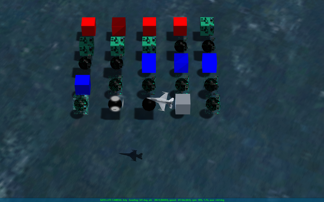
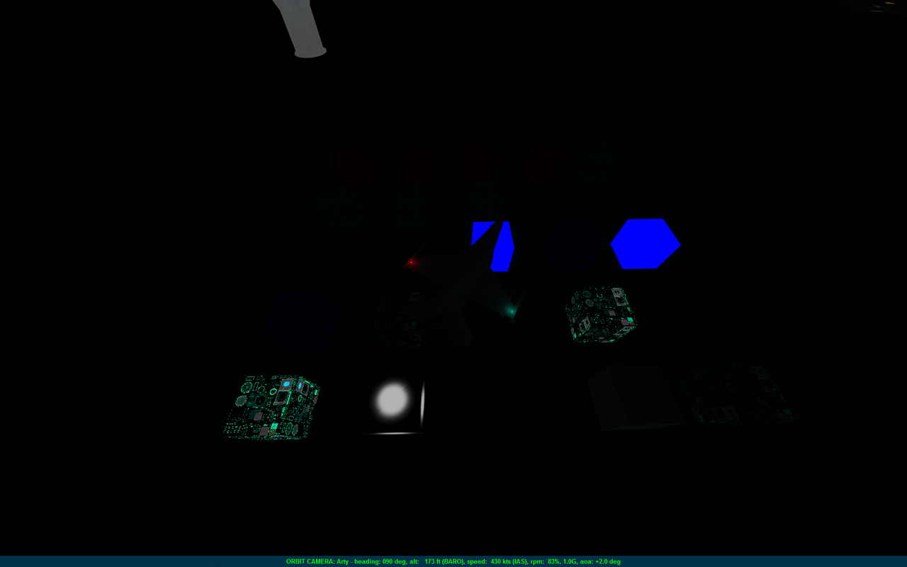
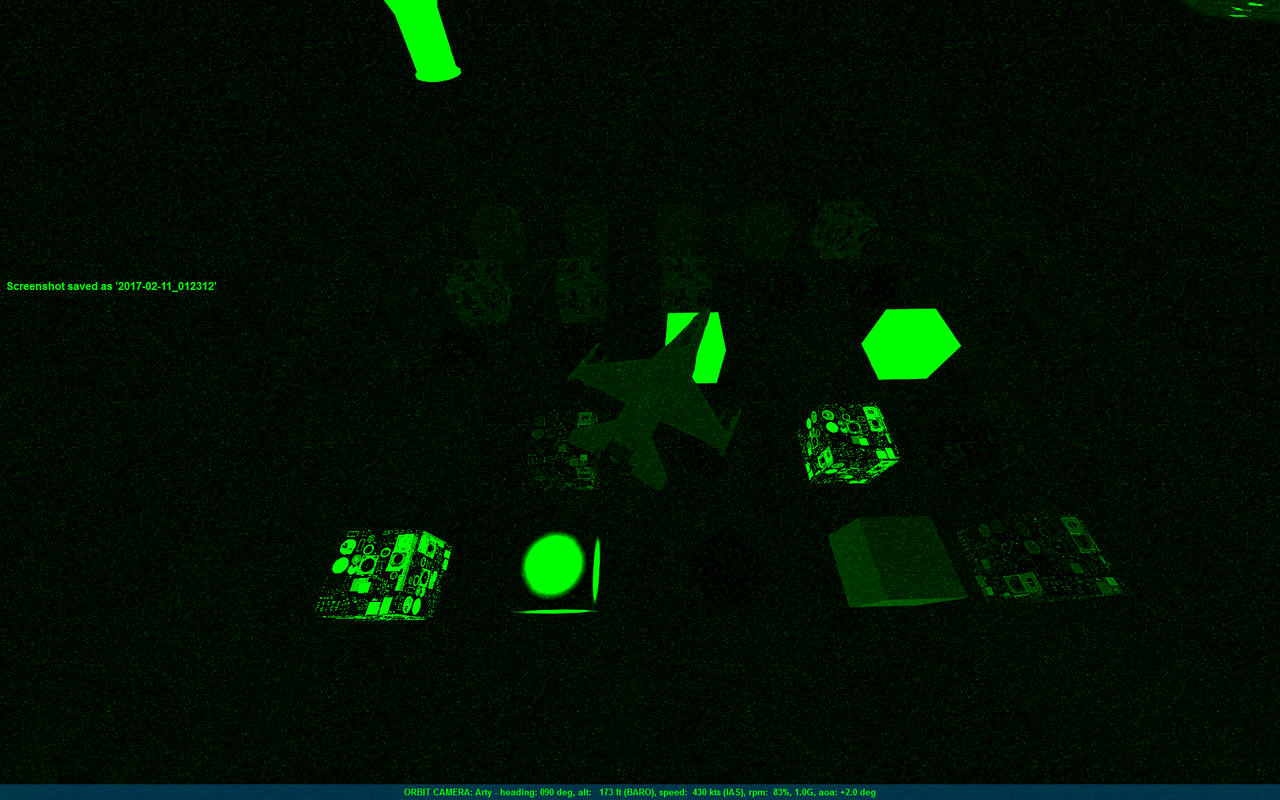
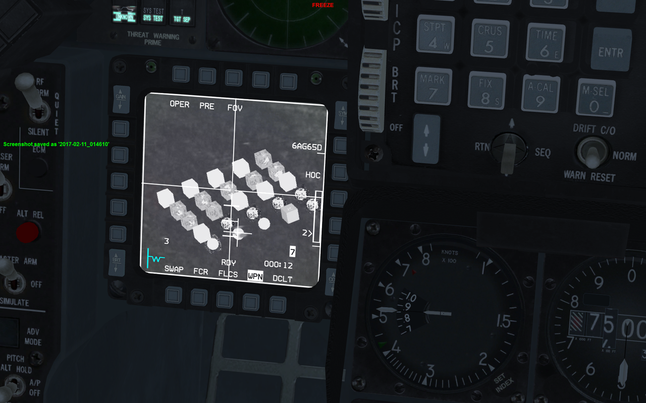
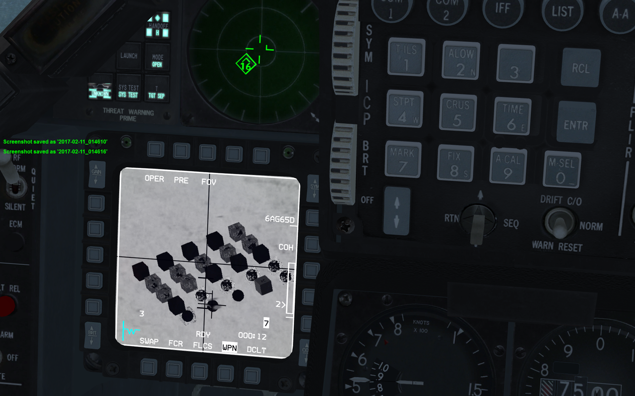
In Game Screen Shots:
DAY
NIGHT
NIGHT with NVG
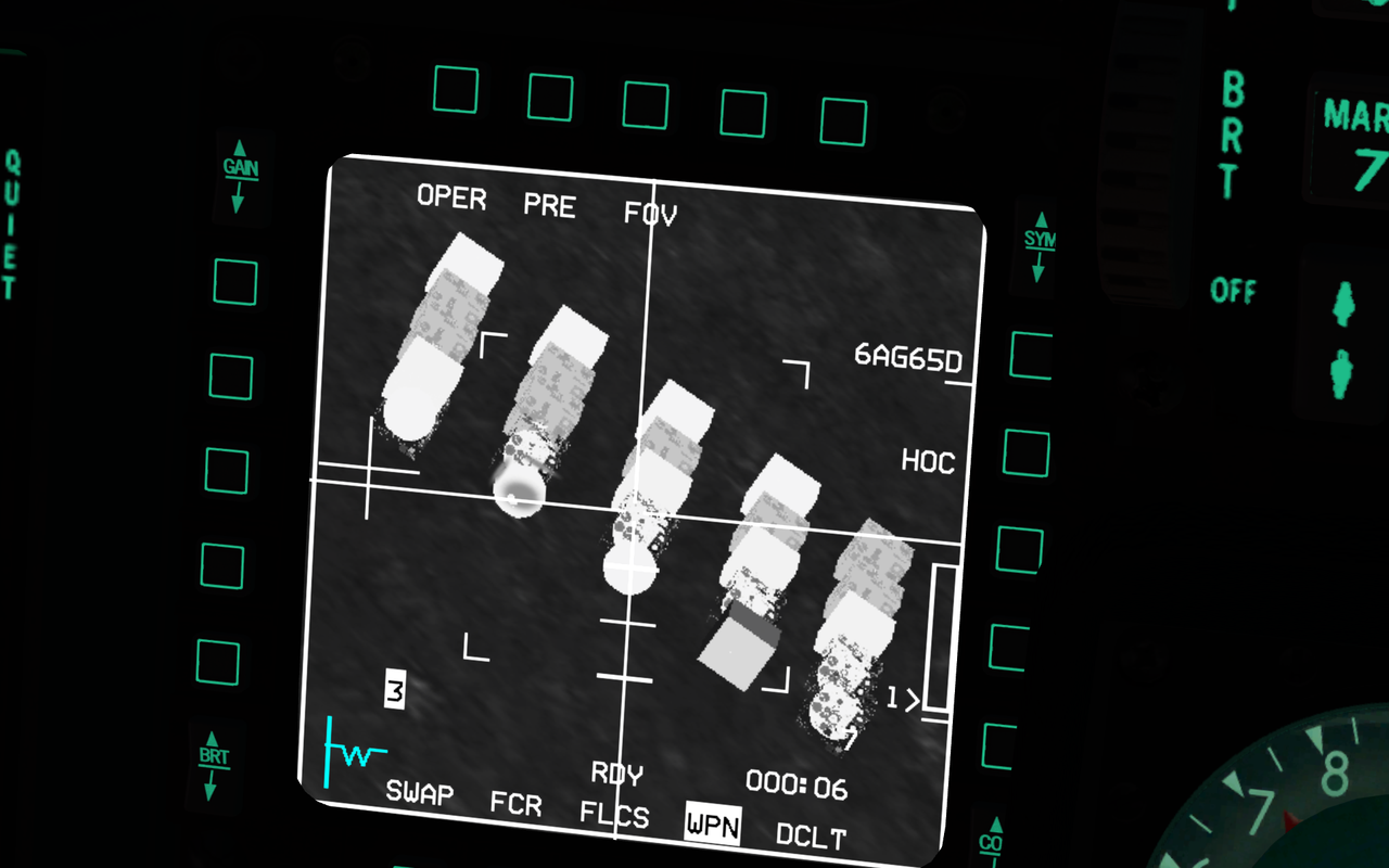
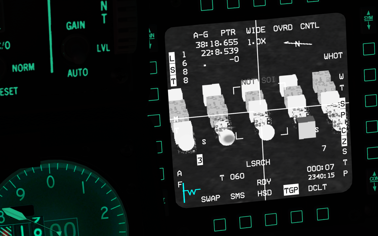
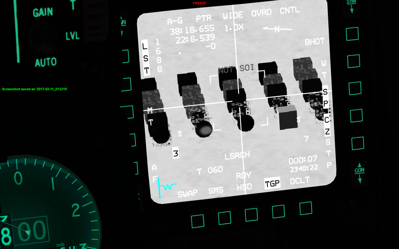
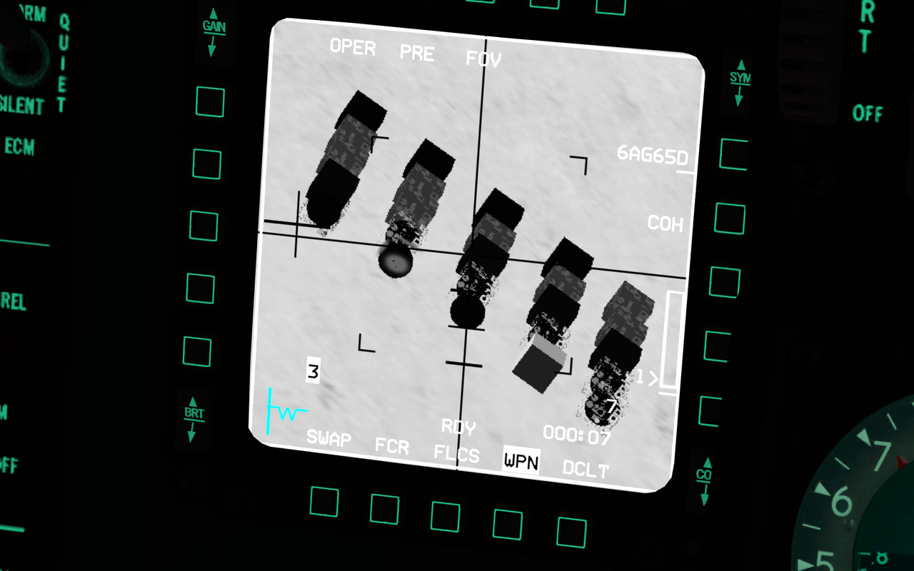
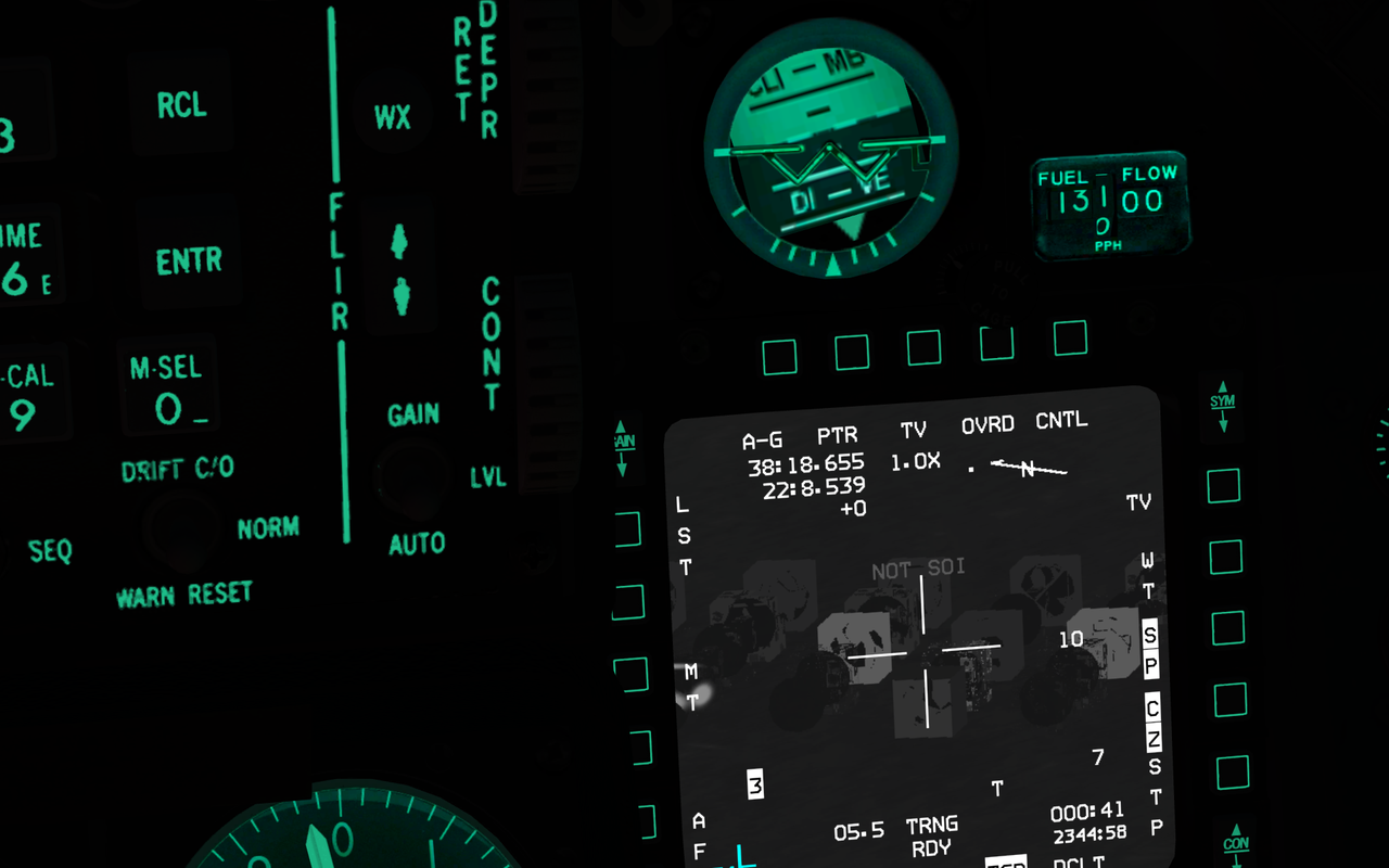
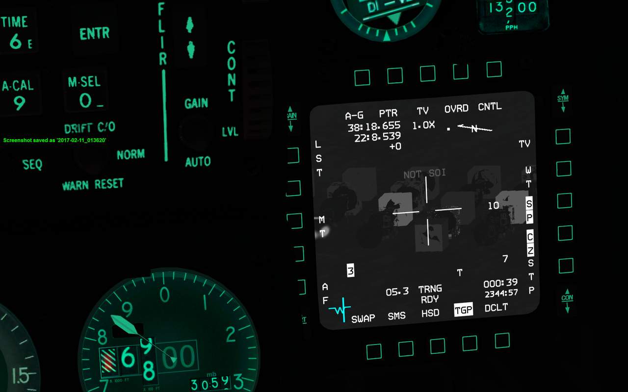
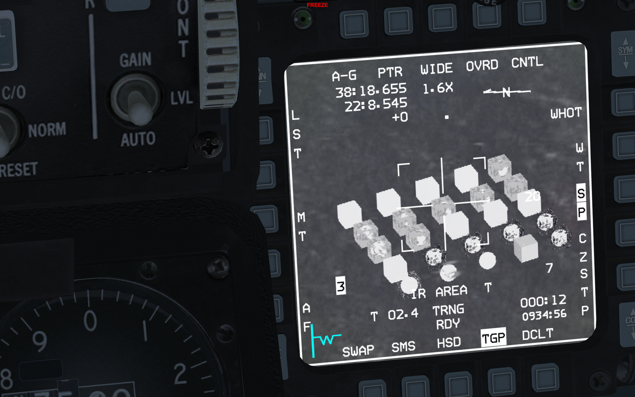
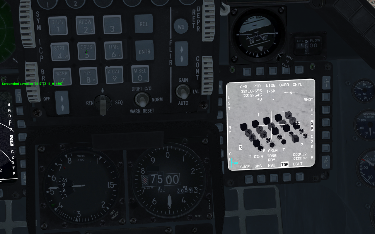
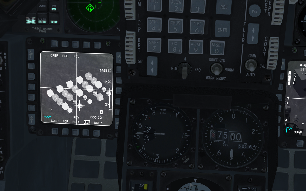
Various from TGP and WPN in various modes:
The 3DS MAX file that I created the LOD is here for you to download if you want it.
And my ptypes excel file is here: https://1drv.ms/x/s!AtJa23BCDEy5gbsPNCJJF5h59JjreQ
All the 3d objects I created them with reference from my excel ptypes file, so I didn’t made any error from Wavey Daves document.
I hope this will be helpful to anyone.
BIG THANX to Wavey Dave for inspiring me with his LOD file… It was a very nice Kickstart m8.
-
The texture is from
C:\Falcon BMS 4.33 U1\Data\Terrdata\objects\KoreaObj\8004.dds
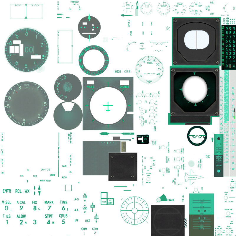
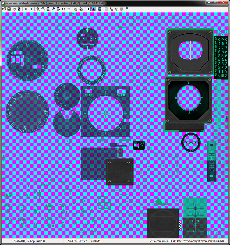
This is the texture Alpha channel:
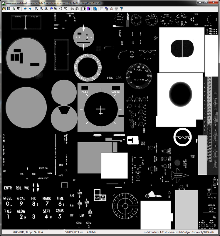
This is the transparency coming from the above Alpha (Black / Grey / White usage):
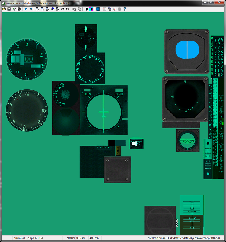
This is the transparency again edited by my to make it easier to understand it:
-
The texture is from
C:\Falcon BMS 4.33 U1\Data\Terrdata\objects\KoreaObj\8004.dds
https://s25.postimg.org/qp548cg23/BMS_Ptypesl003.png
This is the texture Alpha channel:
https://s25.postimg.org/6t94ssz0r/BMS_Ptypesl002.png
This is the transparency coming from the above Alpha (Black / Grey / White usage):
https://s25.postimg.org/pbdhd1gsr/BMS_Ptypesl004.png
This is the transparency again edited by my to make it easier to understand it:
Arty, say we want to make the canopy glass in a model or whatever glass. We have to have some particullar Texture? And if yes give us some details please
-
Arty,
It will be easier to you if you will read with understanding This document.")
-
Arty,
It will be easier to you if you will read with understanding This document.believe me I have read it many many many many times.
I’m not a 3d Modeler - texturer as a profession.
I have little free time and I want to be productive instead of just blind folded looking for the tools to do it.
This document u refer to - Updated as I see cause in the past it was not so detailed IIRC, but still u must try them all to see the effects and to be sure, also headbang many times questioning your self what am I doing wrong?
Small example Per Vertex… Apply a Vertex paint modifier says the document. Well I did. Didn’t work. I had to select the correct options like vertex color and then select Assign… Just adding the modifier by default might be in face selection…
Sooo… yes you will say ain’t obvious? Well m8 not at all. Only for someone that knows it. Call me stupid but few weeks ago I found out that there is a vertex modifier in 3ds.Even my previous post I am sure ain’t clear to many ppl struggling with the beast. And yes they are very very right. Fine example, Manos that asks for the canopy I must have this xx ptype so I must have and a texture? How do I set this texture?
So in many cases and with multi ptype models it is really a good mindjob for ppl novice wanting to help and for stuff that for Falcon gfx Gurus are 1+1=2 but unknown to the rest.Manos Sorry m8 can’t really answer u.
Never done a canopy so by result to know. In theory as u see I try to put in practice things found in the docs.
As I understood from what I have read for the inside looking out u must use ptype 26. Same looks and for the outside looking in. In some post I found that ptype 25 is the correct for canopy… Doesn’t look correct in my findings that I posted earlier.
About the texture now. Looking from in to out u must use a mirroring representation from the cockpit reflection and the scratches.
Looking from out to in u must have the golden filter for example in the f-16’s variants that have that canopy, others have clear Glass.
A trick I remember for dirt in the borders where the glass connects with the metal, play with the transparency and black - dark grey color on the edge in the texture. this will make it look dirty in the borders.I hope Eghi will direct u to the canopy creation document where all details for u r there, and not the doc he posted already in the previous post.
I don’t know if such a doc exists, but shouldn’t it?Edit: Oh for not being misunderstood… I don’t imply that BMS team should do such a doc. Many community members had made canopy and cockpits… I don’t see the doc’s for the way to making them stacking around in the forum helping others…
-
thks PB
-
believe me I have read it many many many many times.
I’m not a 3d Modeler - texturer as a profession.
I have little free time and I want to be productive instead of just blind folded looking for the tools to do it.
This document u refer to - Updated as I see cause in the past it was not so detailed IIRC, but still u must try them all to see the effects and to be sure, also headbang many times questioning your self what am I doing wrong?
Small example Per Vertex… Apply a Vertex paint modifier says the document. Well I did. Didn’t work. I had to select the correct options like vertex color and then select Assign… Just adding the modifier by default might be in face selection…
Sooo… yes you will say ain’t obvious? Well m8 not at all. Only for someone that knows it. Call me stupid but few weeks ago I found out that there is a vertex modifier in 3ds.Even my previous post I am sure ain’t clear to many ppl struggling with the beast. And yes they are very very right. Fine example, Manos that asks for the canopy I must have this xx ptype so I must have and a texture? How do I set this texture?
So in many cases and with multi ptype models it is really a good mindjob for ppl novice wanting to help and for stuff that for Falcon gfx Gurus are 1+1=2 but unknown to the rest.Manos Sorry m8 can’t really answer u.
Never done a canopy so by result to know. In theory as u see I try to put in practice things found in the docs.
As I understood from what I have read for the inside looking out u must use ptype 26. Same looks and for the outside looking in. In some post I found that ptype 25 is the correct for canopy… Doesn’t look correct in my findings that I posted earlier.
About the texture now. Looking from in to out u must use a mirroring representation from the cockpit reflection and the scratches.
Looking from out to in u must have the golden filter for example in the f-16’s variants that have that canopy, others have clear Glass.
A trick I remember for dirt in the borders where the glass connects with the metal, play with the transparency and black - dark grey color on the edge in the texture. this will make it look dirty in the borders.I hope Eghi will direct u to the canopy creation document where all details for u r there, and not the doc he posted already in the previous post.
I don’t know if such a doc exists, but shouldn’t it?Edit: Oh for not being misunderstood… I don’t imply that BMS team should do such a doc. Many community members had made canopy and cockpits… I don’t see the doc’s for the way to making them stacking around in the forum helping others…
Well I do change the ptype through LE where im doing the last fixes and stuff as i told u in previous post. I allready have the material (transparent) set so it exported in ptype 17 so with batch converter i change it to 25 but it would be nice to have it ready as i export the model. Thanks for the answer. Many things would be usefull if written from the modelers that are here in this forum so others will know also.
-
WaveyDave has put this pdf out before and I believe there’s a link to it somewhere, but here it is anyway: http://www.mediafire.com/file/94j0s79qs4zhnxf/Surface_pType_settings.pdf
-
PumpyHead the link u provided is the same as Eghi did. so same commends on that as previous.
Yes this is our bible. But it has a prerequisite that you know basic staff and that you will spend many hours not just learning the Production tool 3ds Max but also how it will be shown - interacting in Falcon World. And we all know that for testing you must not just go to LE or Falcon Editor but inside Falcon.
The quest here is to make things easier for novice users and ease up the struggle with the beast. Create a better more complete reference guide for new guys. BMS dev’s and gfx gurus are up to their head I believe so we all must help in the way we can.
Imagine the surprise the guy that makes the detailed F-14 (Stingray) when he will transit from Blender to 3dsmax and export the model for Falcon. How many new things he must learn and that he will have to adjust almost everything to be shown as they should in Falcon World.
Now ok yes, someone without any knowledge in 3ds max shouldn’t go this path and start creating 3d models. Ok but the practice is different. I don’t see many knowledgeable in 3d ppl producing but the opposite. Guys with no knowledge at all are trying to learn to produce… The learning curve is OMG and in many cases it burns.
The new gfx engine and optimization that BMS provided is not used to it’s full extend. Fine example your wonderful F-16 and other models, they are high poly and the FPS are ok. The Falcon 3d database is good but old and we can all help on this instead of: ok another skin - skinner.
My point is if there are more info, like ready in the plate, guys would easier say, ok I can do that, so contribution would be more. And I’m not talking about contribution only for one theater I’m talking about contribution towards all aspects and specially BMS team.
Another example besides Manos that wants some help on the canopy was optimizing a model to reduce triangles… A simple keystroke knowledge to remove the over too much edges and result to an almost intact model.
So we all are caught up on the ok I don’t have time to educate others or share part’s of my knowledge but on the bottom line it is Falcon’s loss.
-
Almost no one else could have told all these better or more clear… thanks a lot for having pointed it out, Arty. +10000.
Only hope that ‘someone’ will listen and do consequently, because IMHO making things easier isn’t to give away pieces of no one else’s ‘power’, but is sharing knowledge to increase it and grow up.
This heritage could be a major task, and impossible if left to a few or one only good will guy. But it’s also the better way I know to assure a longest life to Falcon - not Free, AF, Open or BMS: Falcon, enough.With best regards,
-
Another find asking for verification or guidance please.
It’s about radius and bounding box to calculate the hitbox and radius dimensions for the model for LE.
If you create the sphere and then use scale then the radius remains to the initial size always regardless the scale you do. So the result in Listener with the max script to calculate the dimensions is wrong if you apply scale.
So the correct way is to set - change the radius value in the sphere properties and just move around the sphere model so to fit the whole model to be exported. Right?
Same applies for the bounding box. Right?Damn I though scale was altering those properties xyz sizes.
So if we scale up our models and then we want to see their dimensions from the properties they are all wrong?
Why doesn’t this sound logical to me?