WIP: F-14 B/D
-
Symphony of victory !

It was you who made the Tomcat for FF 5.5.5 ?
No I only ever produced skins and they used one of my screenshots for the FF installer :D. I only seem to remember that ‘ZAGGY’ had something to do with the original model which is still the one used today in BMS. The original PSDs for that model which I and many others (also HRenner for the current BMS skins) used were created by one ‘Onesimus’ who since then has made quite the career:
http://www.onesimusnuernberger.com/
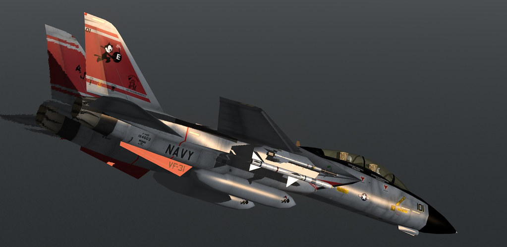
Thanks to Onesimus that old dog of a model is still going strong in 2016 (skin from 2014):
-
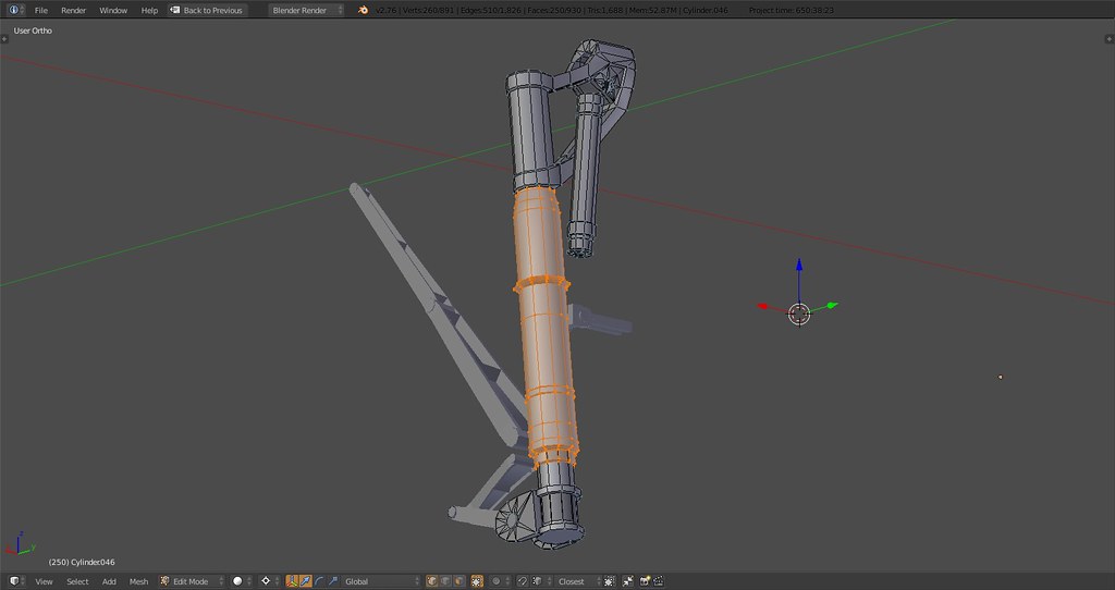
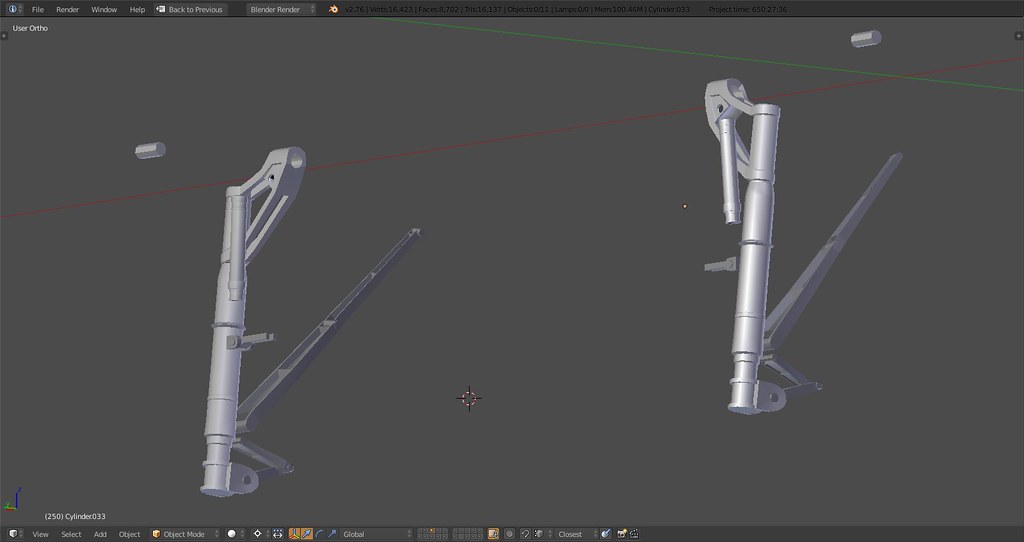
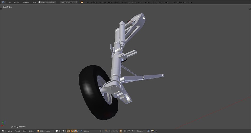
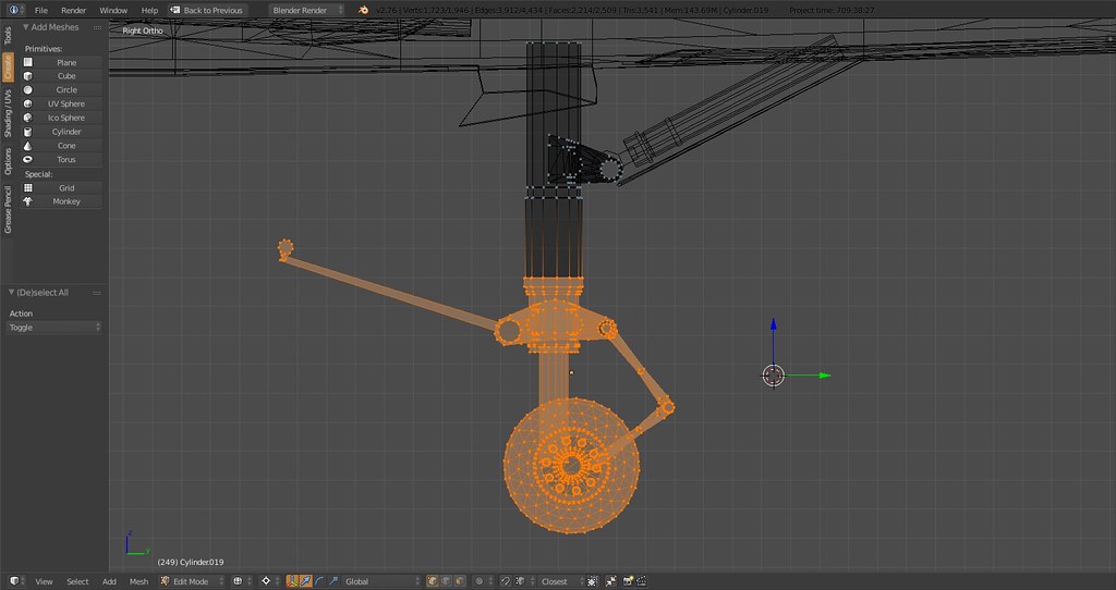
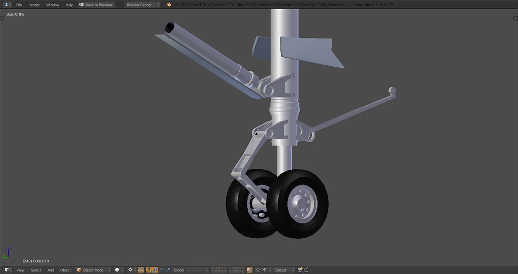
Update on MLG now including main strut, shock absorber, scissor link hinge, angled and rotated into default position:
Highlighted is the main strut lower part
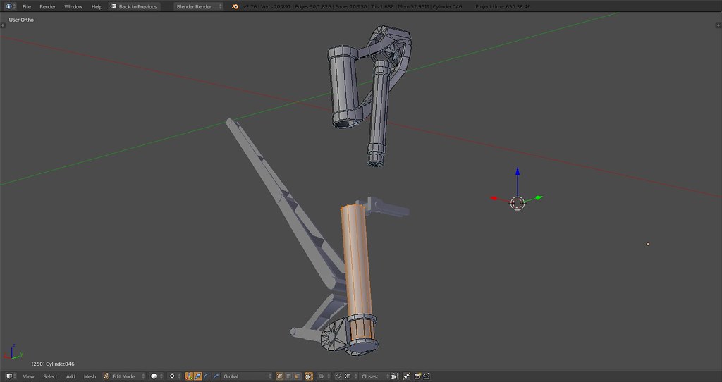
Main strut upper part
-
errrr no I was not joking… As I read in a previous post you mentioned around 14k polys.
As I build my first ship My polys without the detail level I would want is above 20k.
And I was amazed of such a detail level in your model with only 14k and I thought I’m a dumbass lousy 3d modeler, with no good details and way high poly count at the same time.Anyway your model is super and I admire your patience and time on it… It will be an honor and a real joy to fly next to it some time… not in… from outside you can enjoy all it’s glory.
F-14 and Su-27 where my first child time posters cut out from magazines… I also have the Miramar TOPGUN publication with fabulous photos of her…
-
Looking all this progress makes me very proud of your work and very optimistic for the future of F-14 in BMS!! Keep up the good work! Thank you!
-
errrr no I was not joking… As I read in a previous post you mentioned around 14k polys.
As I build my first ship My polys without the detail level I would want is above 20k.
And I was amazed of such a detail level in your model with only 14k and I thought I’m a dumbass lousy 3d modeler, with no good details and way high poly count at the same time.Well to clarify the landing gear ONLY is at 14k. The model without the landing gear and wings is currently at 19k. The wings stand at 15k. So there’s only around 20k tris to shred

Realistically speaking it’ll be possible to land below 40k without compromising on proportions/desired detail on all objects including cockpit, landing gear, wings, surfaces, etc.
Possible below 30k? I’ll try but I doubt it, this aircraft is pretty much double the size of an F-16 in terms of area and easily has twice as many moving surfaces if not more.
-
Well maybe you should compare it with the F-18 model?
I believe those 2 are closer than an F-16.But with my way low experience it will be very difficult to reach such levels with optimization afterwards.
If you have flat surfaces ok but your model is the mother of all sexy curves ever existed… I really hope you’ll get the results you anticipate. Personally I don’t mind for some extra polys for my system as long as there are LOD levels. With Jan’s F-16 I had no problems at all. The thing is if the BMS guys will adopt it to an official setup and why not integrate it alike the F-18.HOT LIST

System Specs:
i7-2600K @ 4.8 Ghz WaterCooled / 32GB Ram. 128GB SSD/1TB SSD / GTX1080Ti 11GB DDR5X / HOTAS COUGAR. TrackIR 4 / 3x24" Mon. (res:5760x1200) / Cougar MFD's / Wheel Pedals / Win 10 64 bit.

-
You said it, it’s about doing it according to BMS specs with the goal of having it implemented. Also keeping in mind that everything is aimed at maximum usability and applicability which is the reason for the poly limit in the first place which I totally am in line with.
In terms of comparison my benchmark is actually WaveyDave’s Tornado as it is a twin engine, swing wing fighter of comparable dimensions and he put together a smooth, beautiful and highly optimized model with lots of details and high degree of immersion and that all-in below 30k.
I don’t expect to have the skill or experience to make that happen here but I’ll try.
-
Go ahead, I think that you can inside the proper limits…

Nikos. -
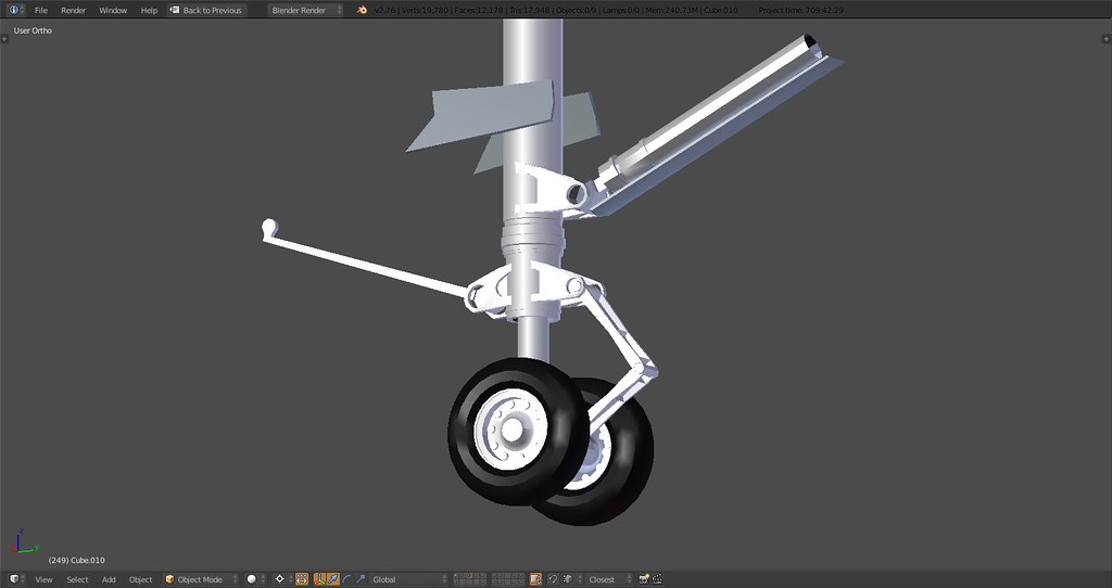
Got a little carried away with authenticity on the MLG, we might just get ourselves the most authentic landing gear on a virtual Tomcat yet without blowing the tris count
")
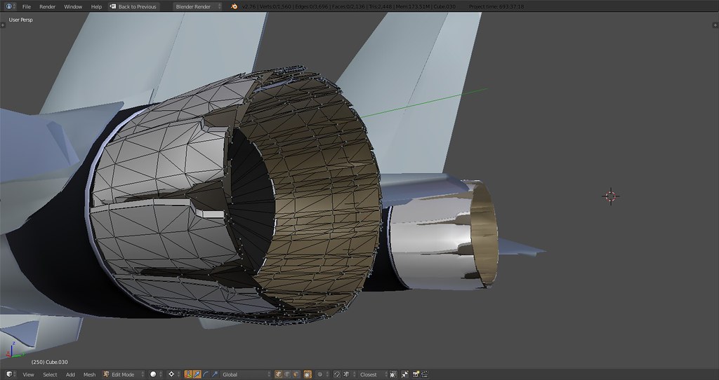
That being said I needed some distraction from the dampers, hinges and shock absorbers so I spent some time researching how people model engine nozzles and tried it myself…

Wicked eh?
I modeled one plate, later added the extrusion on one of the sides and then duplicated part of the inside and added two more layers to get the desired effect.

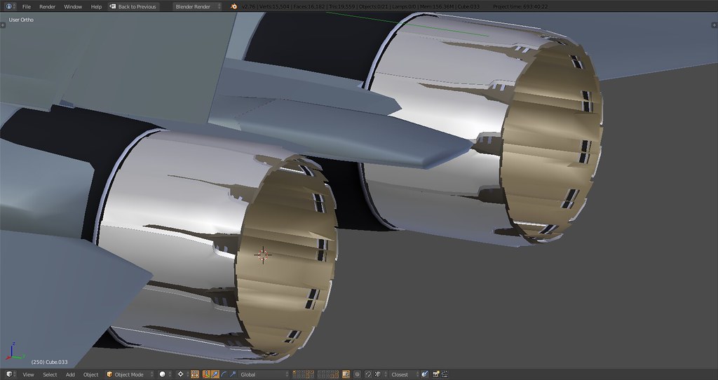
Those rings will probably later be integrated into the exhaust nozzle plates on the inside…
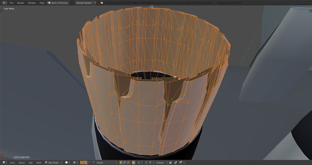
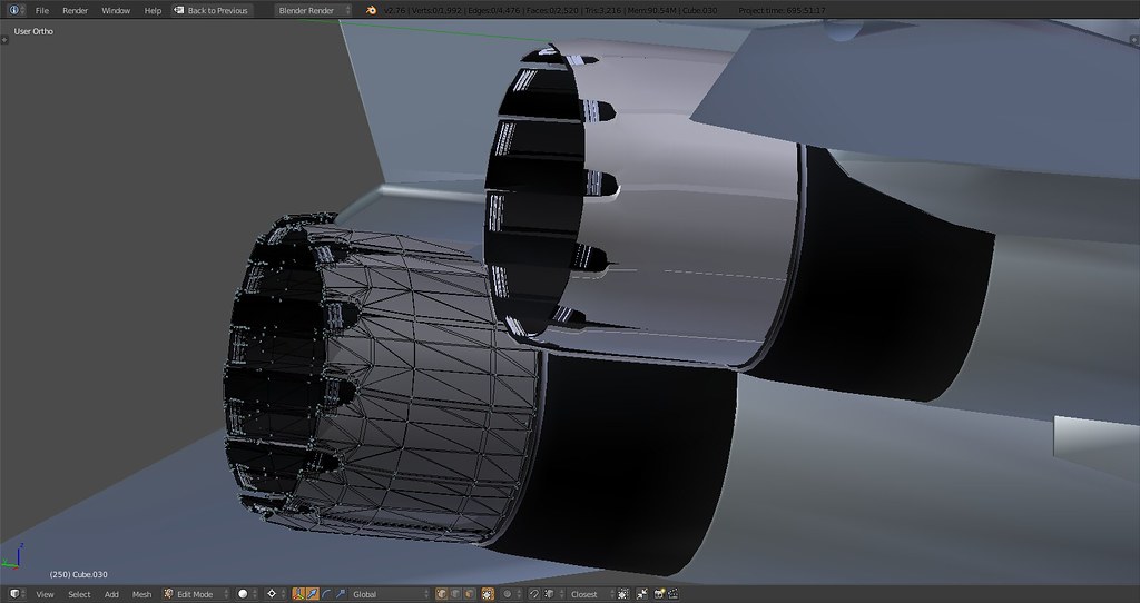
Close up
Basically I did one nozzle with all plates and details and then connected the backframe vertices to the center point of the engine bay, then duplicate and rotate the other 11 nozzles around that point. Probably did that about 20 times following all the corrections
GE, Baby.
-
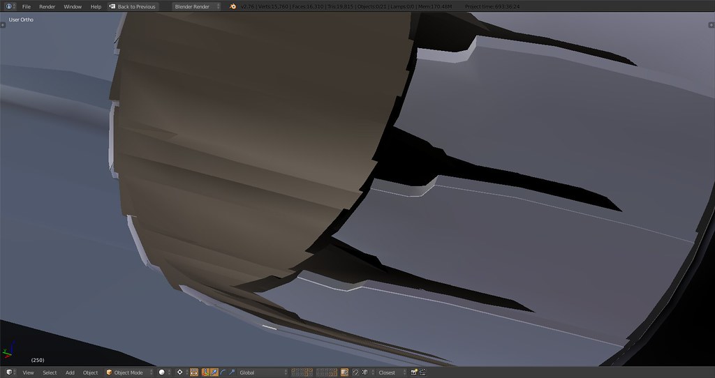
There’s actually only two inside plates I just realized whilst looking at my books. One directly below the outside nozzle and one with slight indents next to it, multiplied by 12 and rotated around it should then look like a tightly sealed inner outlet and slightly seperated outside nozzles. Correction coming up…even though I love the convoluted look of that plate mayhem the way it is now.
-
Really impressive :bowd:
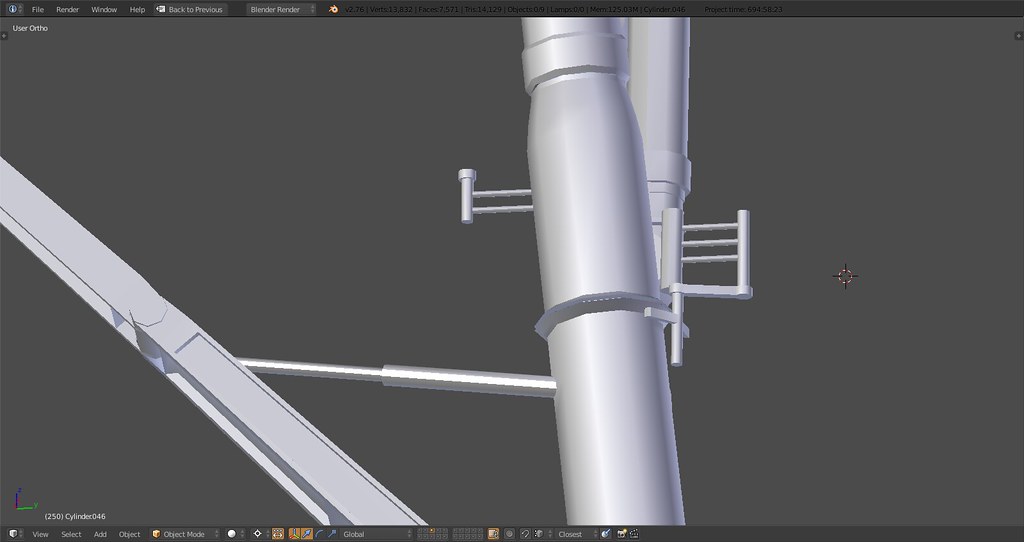
There’s even the “not very well-known blocking T” on the main gear…. As much to say concerning these GE F110’s nozzles -
@SEG:
Really impressive :bowd:
There’s even the “not very well-known blocking T” on the main gear…. As much to say concerning these GE F110’s nozzlesThere is, I mentioned that a couple pages back but no one seemed to notice :D. The corresponding ‘hole’ in the fuselage will be there as well.
-
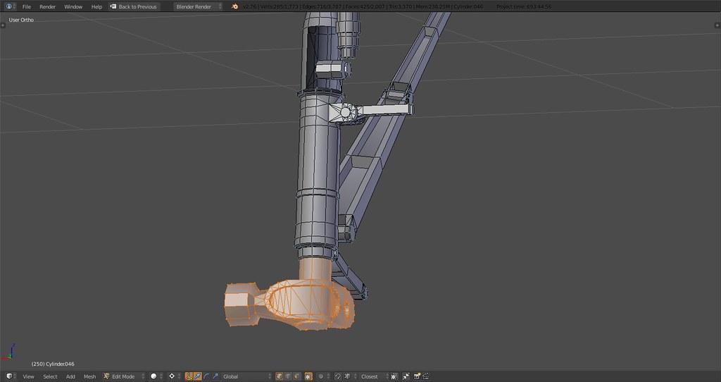
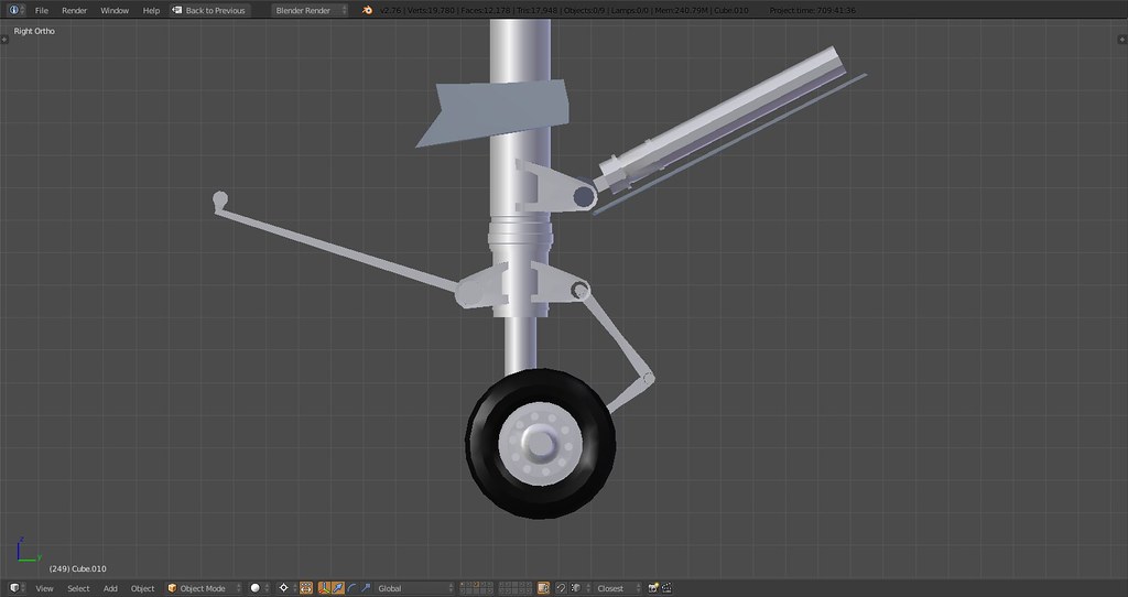
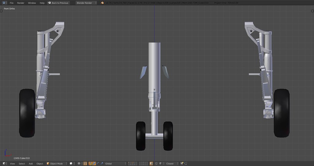
MLG:
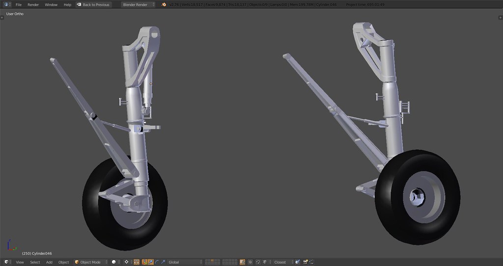
Some parts aren’t connected yet and the tires need some downtrimming so there are some tris to shed…prolly land at around 6000k for the main gear.
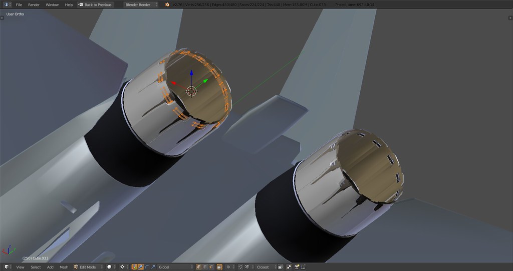
Nozzles now with only two inner parts:
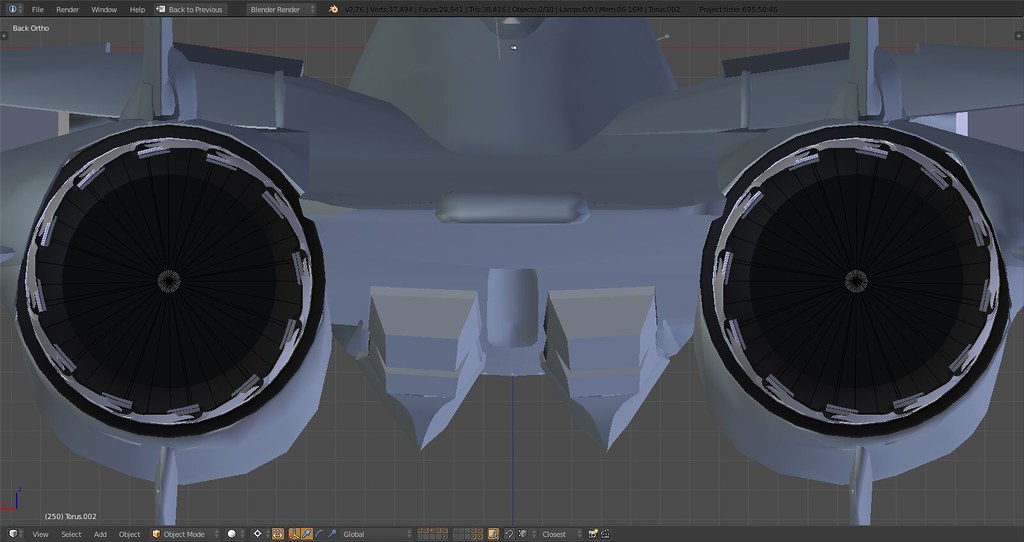

The ‘rings’ now sit on top of the second inside part of the engine outlet instead of one full ring all around.
-
Far above of what we dreamed…
-
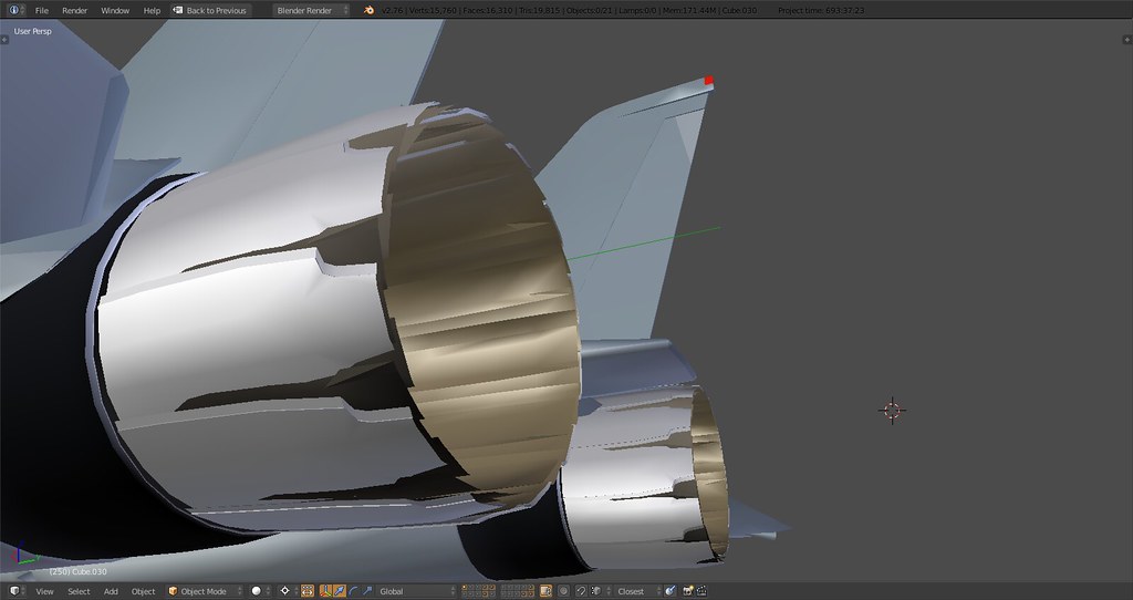
The F-110 nozzles are not mirror images but if there is a Falcon game engine restriction I understand. Right now it looks like the nozzles are mirrored off each other, they should be the same.
-
The F-110 nozzles are not mirror images but if there is a Falcon game engine restriction I understand. Right now it looks like the nozzles are mirrored off each other, they should be the same.
Not sure I catch your meaning. The nozzles are all the same (12x left and 12x right), duplicated off of the first one. There is no mirroring or other modification involved. The only asymmetry about the nozzles is the indentation on the top side as on the real thing. Most GE-F110 nozzles are modeled asymmetrically either due to insufficient research, errors or modeling compromises.
Maybe I’ll have to change them later on when it comes to animation but for now they’ll stay in their ‘original’ shape.
In case you’re referring to the mirror across the y axis you’re right they’re mirrored atm. Can’t apply a mirror and fix this (and others) until all details are finalized.
-
It’s nice isn’t it?
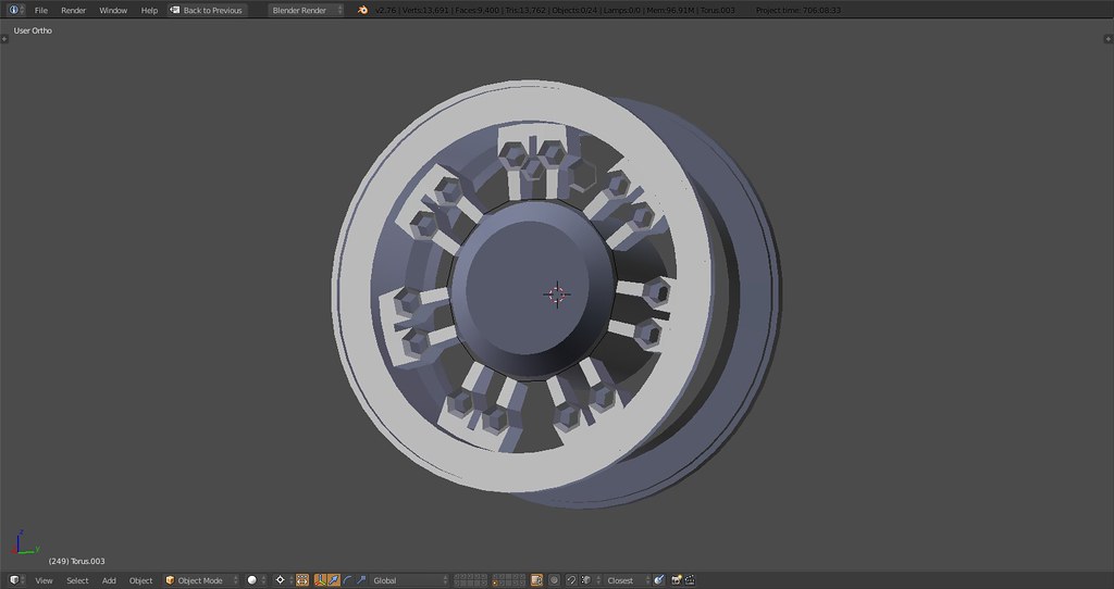
Yeah, at 2000+ tris I probably moved that part to the nice but another time layer :). Instead worked on mesh optimization and reduced the number of tris per wheel to under 1000:
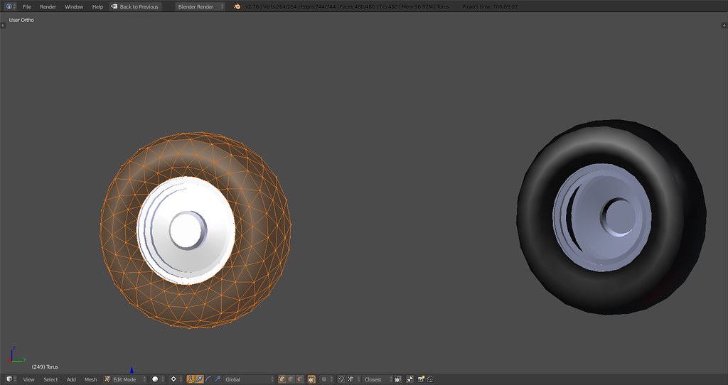

Before: 12.000 After: <3.000 - I like.
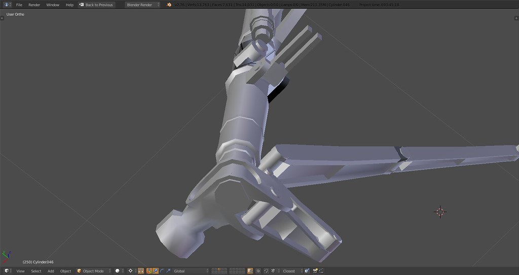
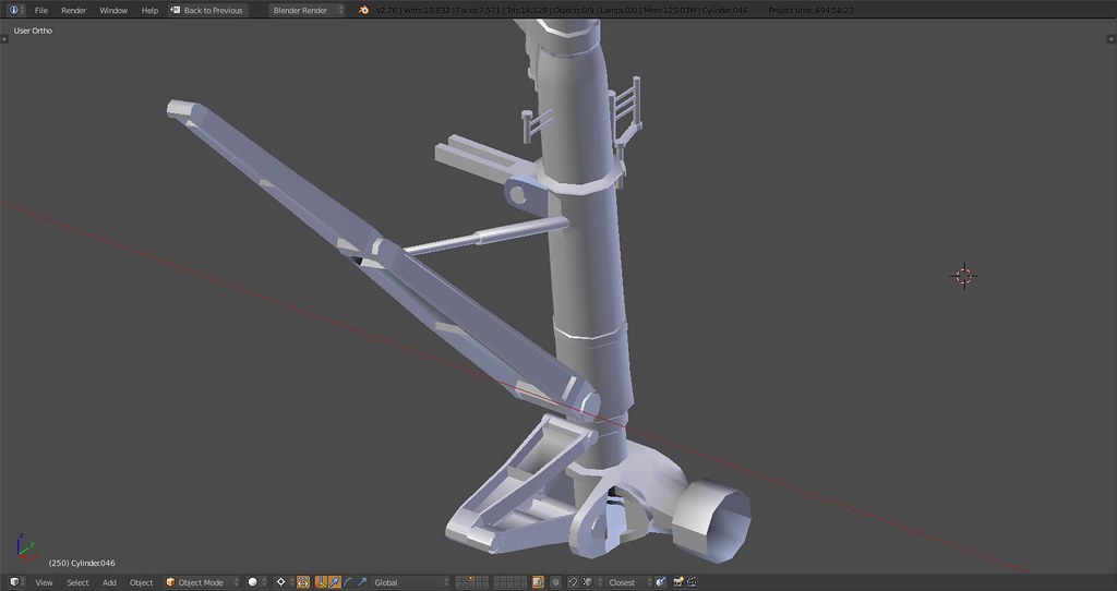
Then proceeded to the nose gear and made some progress. Parts have to be connected still but overall it’s getting close to the real thing. The whole geometry of the strut was wrong though which I only found out after I attached the nose gear strut actuator - corrected now.
That nose gear is a beautiful assembly once it comes together. Looking forward to ‘welding it’ into one piece including landing light, the box and other details.
FYI you see the gear in the compression stage that a fully fueled, semi loaded Tomcat would have on deck. Main landing gear is almost fully compressed and front has enough room to kneel otherwise also compressed. Before it’s rigged it’s a pain to move all the parts…
-
Stunning. Do the nose gear indexer lights work in BMS? That would be fun to see from the flight deck.
I really can’t wait to see this thing in action…I suspect that some of the virtual VFA squadrons out there will become virtual VF squadrons in a hurry.
")
-
The F-110 nozzles are not mirror images but if there is a Falcon game engine restriction I understand. Right now it looks like the nozzles are mirrored off each other, they should be the same.
Stingray, I think what Turkeydriver ment is that your engines (on the images at least) have different petal “spin” - left engine spins anti-clokwise, and right spins clockwise. I think the petals should be arranged in the same direction… (view directly from behind)
-
Stingray, I think what Turkeydriver ment is that your engines (on the images at least) have different petal “spin” - left engine spins anti-clokwise, and right spins clockwise. I think the petals should be arranged in the same direction… (view directly from behind)
See last part of my post, what you’re describing is a mirror across the y axis of the plane. Meaning the left engine outlet and nozzle is mirrored horizontally across the axis thereby resulting in a ‘clockwise’ spin.
Currently the nozzles are part of the main fuselage object which means the mirror is applied to it as well. As long as the vertices on any part of the main body aren’t in their final position the mirror cannot be applied to make it one part because then any modification of any vertices will not be mirrored and potentially result in asymmetry.
To make it clear I know about the issue, it will be sorted out once the main body mirror is applied and then the outlets and nozzles will be separate parts and left will be duplicated and moved to the right. This issue applies to many parts of the model which is simply a result of modeling.