WIP: F-14 B/D
-
Does anyone by any chance know the max and min rotation limits on the horizontal stabilizers and rudders? I have all other limits for wing surfaces and doors but can’t find this anywhere.
-
Does anyone by any chance know the max and min rotation limits on the horizontal stabilizers and rudders? I have all other limits for wing surfaces and doors but can’t find this anywhere.
Rudder : +/- 30° maximum. Can be further limited depending on AOA and landing gear/ flaps on. With DFCS on, limited to 19°.
Horizontal stabilizers : EDITED : actually, +33° (pitch up) / -10° (pitch down).
Source : F-14 NATOPS (Page 2-100 and up). -
Rudder : +/- 30° maximum. Can be further limited depending on AOA and landing gear/ flaps on. With DFCS on, limited to 19°.
Horizontal stabilizers : EDITED : actually, +33° (pitch up) / -10° (pitch down).
Source : F-14 NATOPS (Page 2-100 and up).Sweet! Thanks, didn’t think to check the NATOPS now that you mentioned it.
-
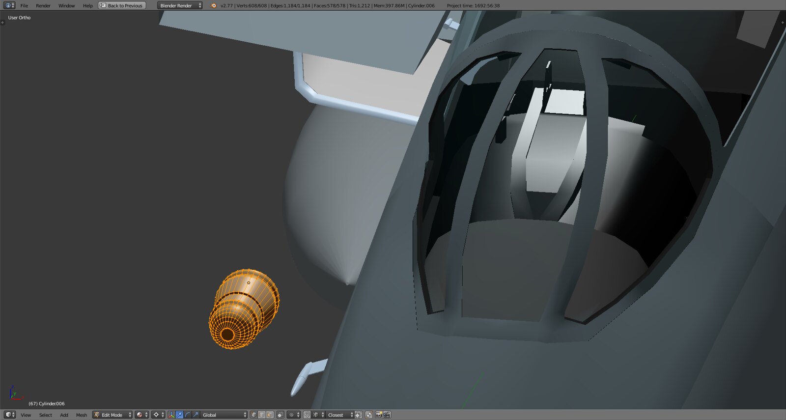
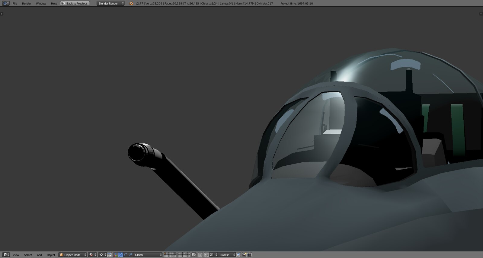
Now that the pit is done (pending the sticks and some minor adjustments) it’s on to the wings and surfaces and actually to the end of hard surface modelling in Blender. So now optimizing and ‘perfecting’ the mesh(es) and getting everything to work (also started on the refueling probe
") is in focus as well as modeling the insides like the inside of the wing body and glovebag etc.
is in focus as well as modeling the insides like the inside of the wing body and glovebag etc. -
If this can help you for the refueling probe, check this out
 :
: -
Duuude that is an awesome resource. Very useful for overall dimensions and animation. I’ve seen that before at some point but couldn’t find it when I was scouting for refs yesterday. Thanks a bunch!
Here’s what I started 2 days back
Luckily the refueling probe is one of the very few parts of the Tomcat that is fairly standard and simplistic in nature :).
-
Duuude that is an awesome resource. Very useful for overall dimensions and animation. I’ve seen that before at some point but couldn’t find it when I was scouting for refs yesterday. Thanks a bunch!
Here’s what I started 2 days back
https://c1.staticflickr.com/3/2202/32879365246_1898d3511e_h.jpg
https://c1.staticflickr.com/3/2300/32879364866_ba7901f984_h.jpg
Luckily the refueling probe is one of the very few parts of the Tomcat that is fairly standard and simplistic in nature :).
Hello!
Great work of yours! Nevertheless I feel your refuel drogue maybe has a bit too much triangles?
Do you think it’s worth spending so much tris in it?
Kind regards,
Radium
-
Hello!
Great work of yours! Nevertheless I feel your refuel drogue maybe has a bit too much triangles?
Do you think it’s worth spending so much tris in it?
Kind regards,
Radium
Thanks! Of course not but with easy to model things like that I like to create something nice in the beginning so I can enjoy its look throughout the modeling process while dealing with the latches, doors and general shape, dimensions and angle. Later on I trim things down to something a bit more reasonable.
Having a refueling probe with more polys than the entire cockpit including the seats would be interesting :D.
-
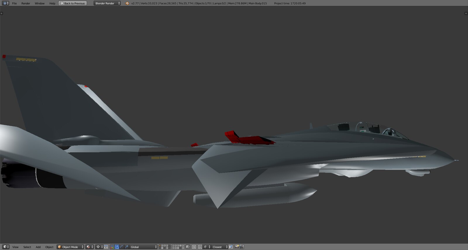
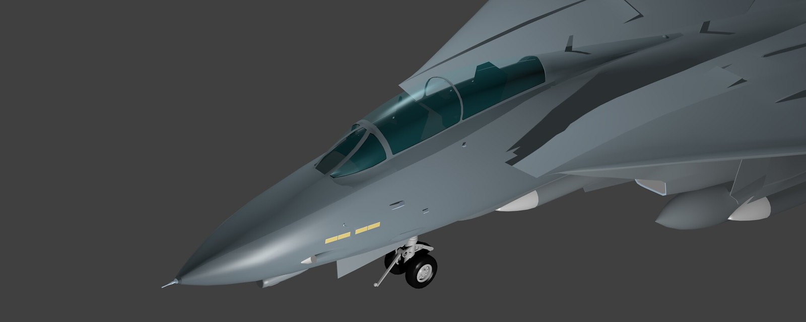
Great progress, Stingray, but I have to make a suggestion. It’s a pain in the ass, but I think you should consider re-working the triangles on the nose into quads for better smoothing. They often look “wrinkled” when shaded and BMS unfortunately will make this worse. It looks like you did a lot of pushing and pulling of vertices to get the shape you wanted, but unfortunately the side effect is the uneven mesh. Just a suggestion, really glad to see your good work on this model!
-
Great progress, Stingray, but I have to make a suggestion. It’s a pain in the ass, but I think you should consider re-working the triangles on the nose into quads for better smoothing. They often look “wrinkled” when shaded and BMS unfortunately will make this worse. It looks like you did a lot of pushing and pulling of vertices to get the shape you wanted, but unfortunately the side effect is the uneven mesh. Just a suggestion, really glad to see your good work on this model!
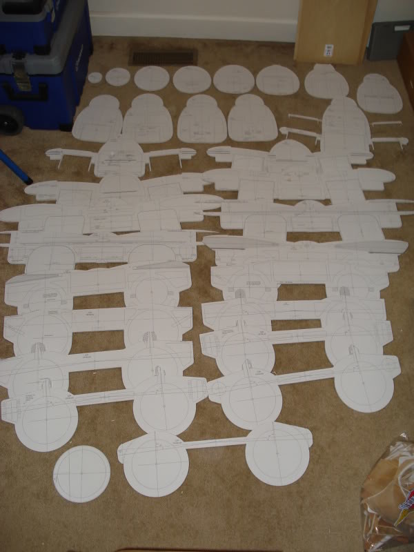
Please do make suggestions, always appreciated. It’s not really a pain, I can do that in 10 minutes as I’ve used a bunch of circles and vertical outlines to build the fuselage as they do in RC modeling so no problem to convert it to quads without losing the general outline. To give you an idea this is what I’m talking about (image courtesy of Thomas W. at rcuniverse):
I noticed the wrinkled nature of the mesh especially along the sides of the fuselage many times and always wondered how exactly I’m gonna get rid of that in the end. So just so I understand correctly you’re basically suggesting to convert it all to quads and align them so that when they’s triangulated (which they inevitably will right?) the triangles fall on one flat rectangular plane and therefore have no extruding edges?!
-
Yes! Exactly. It’s difficult to do manually, so you may end up having to more or less redo it, but you want an even grid of quads. Although everything does eventually get converted to quads, working in triangles makes it very hard to maintain a smooth shape for the rendering engine to shade. It’s especially noticeable with cylindrical shapes like a fuselage. Even the tiniest misalignment of a vertex results in the wrinkled look of misaligned normals! (I’ve learned this by screwing it up, myself.)
Obviously a simple model, but check out the clean grid-like quads of this model. It becomes more difficult to do when you have to consider things like the gunport and formation lights, but it’s still possible.
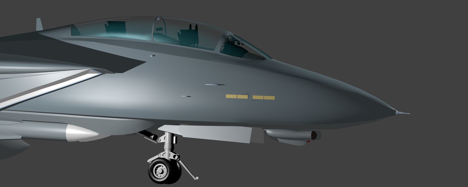
https://www.turbosquid.com/3d-models/f-14a-tomcat-wolfpack-max/779951I can see in this screenshot, for example, that there are visible seams between your faces around the gunport causing you additional problems. You’ll need to weld those vertices together.
https://www.flickr.com/photos/96028865@N04/32052152034/Again, I would recommend redoing that whole section of the mesh. It’s good that you haven’t started unwrapping/texturing yet, as this will be much harder to stomach once you’ve begun that process. The hardest part will be joining it to the canopy frame without distorting the topology too much. I recommend taking a cross-section near the intakes, and gradually extruding forward, refining the shape (as little changes as needed to match the basic profile of your current nose,) and keeping everything in quads.
-
…Although everything does eventually get converted to quads, working in triangles makes it very hard to maintain a smooth shape for the rendering engine to shade.
You mean: “everything does eventually get converted to triangles” right? BMS doesn’t have any adaptive tessellation, does it?
Stringray: To smooth things out I usually try to select a patch of vertexes then w -> smooth. That might help with the ripples. Are you using the edge-split modifier? If so, are there any edges unintentionally marked sharp?
Also, might be a good idea to keep a super high-res mesh around in case BMS adds normal mapping at a later date (again, they don’t do that yet, do they?). Then the normal map could be baked from the high res mesh, then applied to the lower res one. Though I wonder if panel seams might be the best case for using normal maps in flight sims. Might even be able to get away with just using a monochrome bump map for those.
-
Yes! Exactly. It’s difficult to do manually, so you may end up having to more or less redo it, but you want an even grid of quads. Although everything does eventually get converted to quads, working in triangles makes it very hard to maintain a smooth shape for the rendering engine to shade. It’s especially noticeable with cylindrical shapes like a fuselage. Even the tiniest misalignment of a vertex results in the wrinkled look of misaligned normals! (I’ve learned this by screwing it up, myself.)
Obviously a simple model, but check out the clean grid-like quads of this model. It becomes more difficult to do when you have to consider things like the gunport and formation lights, but it’s still possible.
https://www.turbosquid.com/3d-models/f-14a-tomcat-wolfpack-max/779951I can see in this screenshot, for example, that there are visible seams between your faces around the gunport causing you additional problems. You’ll need to weld those vertices together.
https://www.flickr.com/photos/96028865@N04/32052152034/Again, I would recommend redoing that whole section of the mesh. It’s good that you haven’t started unwrapping/texturing yet, as this will be much harder to stomach once you’ve begun that process. The hardest part will be joining it to the canopy frame without distorting the topology too much. I recommend taking a cross-section near the intakes, and gradually extruding forward, refining the shape (as little changes as needed to match the basic profile of your current nose,) and keeping everything in quads.
It’s probably my bad because I’m too open and transparent with my WIP that sometimes people get the impression it’s the final product or that I missed something. I get what you’re saying, thanks for the detailed description. I am aware of the issue and will take care of it. Like I said it isn’t difficult at all especially when you know some shortcuts in Blender when it comes to aligning vertices, smoothing out lines and sections on a fuselage and so on so it’s really not a big deal.
Thing is there are many things unfinished or I haven’t decided on them yet. Like the seams you’re referring to. Up until recently I worked with a mirror. Now that doesn’t work when you have an asymmetric part like the gunport and cooling duct on the starboard side. So I disconnected that part and made it a separate object so it wouldn’t get mirrored hence the seam - can’t weld one vertice to another one that doesn’t exist right?
At some point I will put something up and invite each and every observer to tell me what they’re noticing or any inconsistency or issue however miniscule it might be that appears. That point is not now.
Don’t get me wrong I appreciate the input but now that I see in detail what you mean I realize lots of these things are on the todo list already or simply not an issue like a seam that’s not really there.
-
You mean: “everything does eventually get converted to triangles” right? BMS doesn’t have any adaptive tessellation, does it?
Stringray: To smooth things out I usually try to select a patch of vertexes then w -> smooth. That might help with the ripples. Are you using the edge-split modifier? If so, are there any edges unintentionally marked sharp?
Also, might be a good idea to keep a super high-res mesh around in case BMS adds normal mapping at a later date (again, they don’t do that yet, do they?). Then the normal map could be baked from the high res mesh, then applied to the lower res one. Though I wonder if panel seams might be the best case for using normal maps in flight sims. Might even be able to get away with just using a monochrome bump map for those.
Thanks man, you actually told me that before :D. Thing is I had this issue and solved it already on the wings and the glovebox. The way I did it was to basically create a multitude of horizontal lines usually along the x axis (straight or curve) and have them trace the shape I’m trying to model. Then I align the vertices along the lines and the result will always be aligned quads after aligning the vertices along corresponding vertical lines along the y axis. That approach never failed me and always takes care of ALL misaligned or bad topology.
I’ll do that on each and every surface before I move to Max anyway but now would be just too early to do it cuz half the geometry (exaggerating but you never know) might get changed anyway.
-
Kneel, Baby.
Tomcat does it seamlessly :D. There’s about 10% left in terms of room to collapse, have to check ref pics to see how far down it actually goes when attached to the catapult.
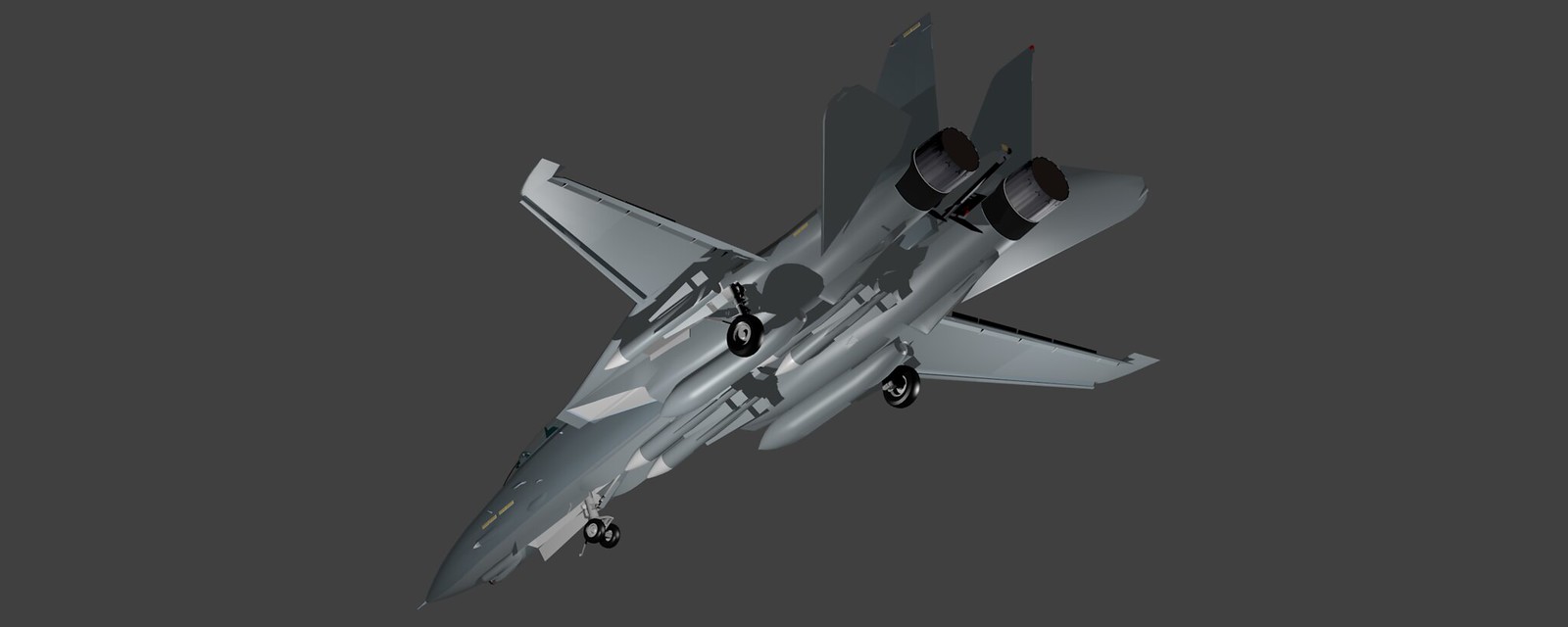
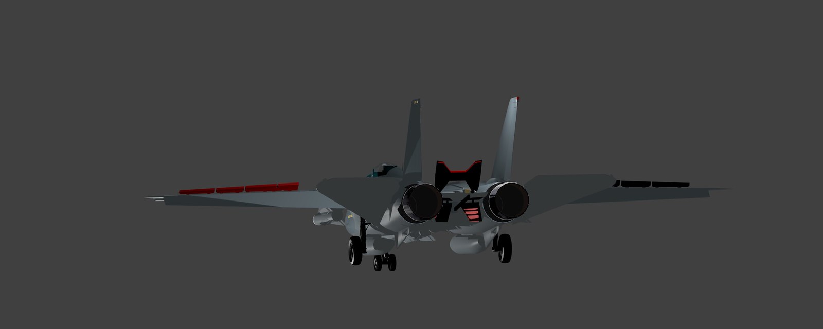
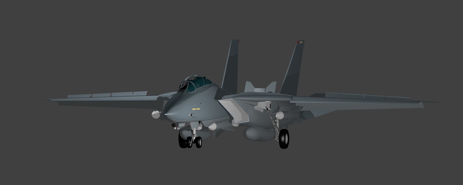
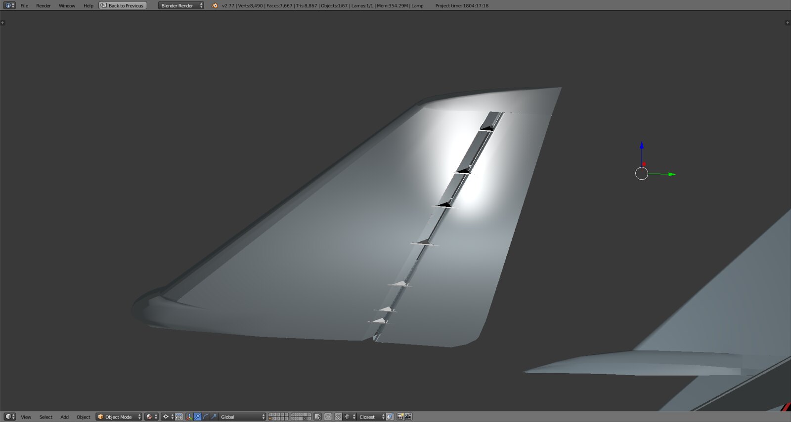
Started finalization of geometry and integration of all moving surfaces. Only group done so far is the landing gear doors. The surfaces have been completely smoothed out and welded, extruded in closed position to ensure fit and then disconnected as separate objects and assigned rotation axis and limits. It’s the only way I can open and close them at this point to finish the work on the model without losing my zero point positions every time I open something. Plus it’s a nice exercise in terms of 3D think :).
Eagle Eyes among you will notice the closed ‘cove door’ wrapping itself around the flap hinges on the main wing. All surfaces are at max so Flaps (main and aux, they’re two separate parts) at 35deg, spoilers at 55deg, slats at 17deg and airbrakes at 60deg. The eyebrow door has been connected to the flap but not yet made movable. I’ll build the wing insides and add some more detail and take some closeups of that next.
-
-
-
IDon’t get me wrong I appreciate the input but now that I see in detail what you mean I realize lots of these things are on the todo list already or simply not an issue like a seam that’s not really there.
No worries, just some input!
You mean: “everything does eventually get converted to triangles” right?
Yes.
-
No worries, just some input!
Yes.
All good, I’ll for sure get back to you once I refine the front fuselage section. The tricky thing is as you pointed out stuff like the gunport, cooling ducts (NACA) and anti collision lights. If you have any input as to how to cleverly arrange the geometry in order to avoid the distortions when rendering it’d be much appreciated! The port side as you can see in the render is not really an issue but starboard is very messy :).
-
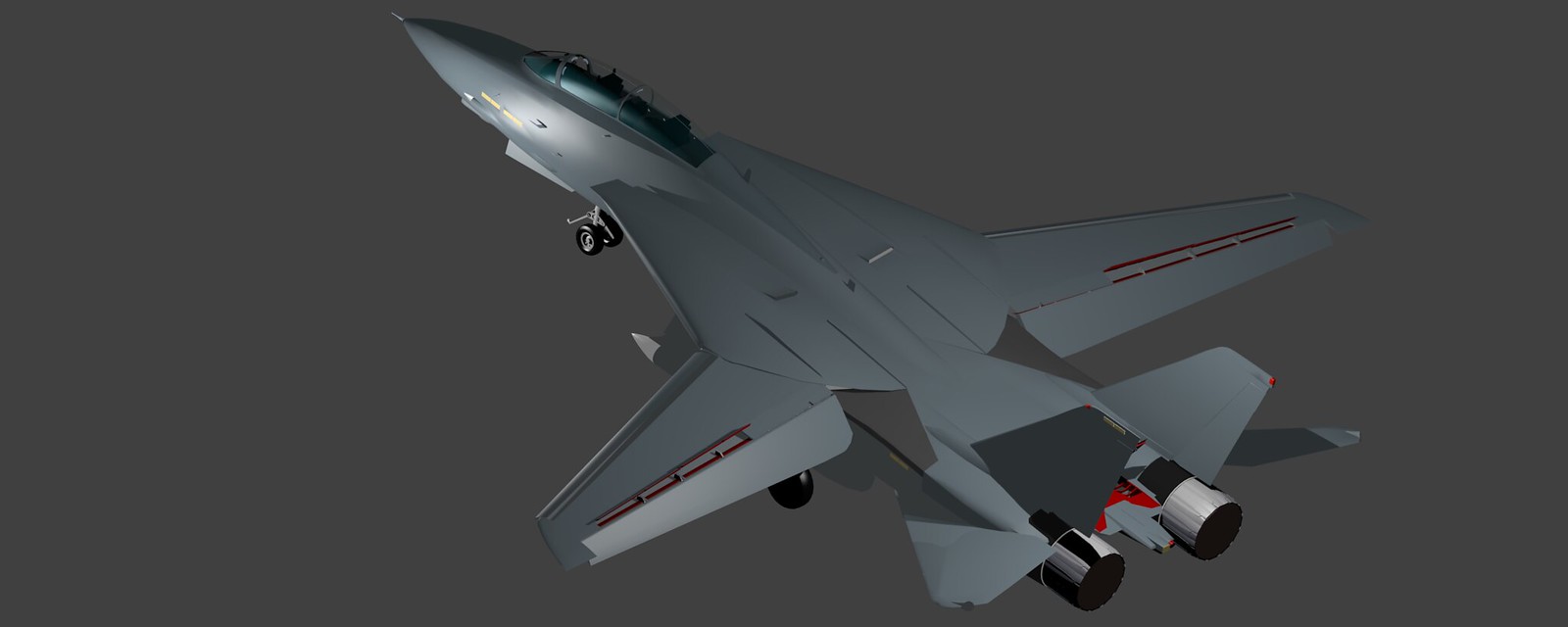
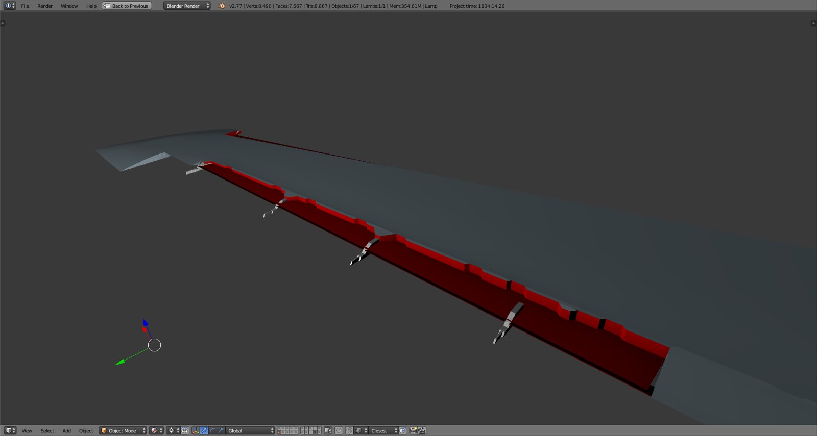
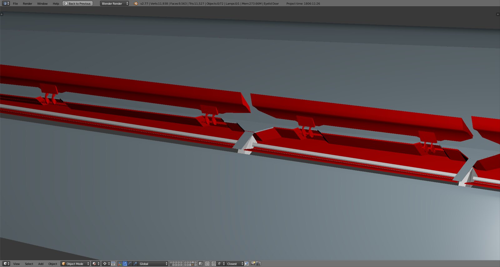
Finally getting to ‘recycle’ some of the parts I modeled a loooong while ago such as the spoiler hinges and some other parts. Flap hinges will follow once I got the eyebrow door separated.
I modeled the wing in such a way that all three ‘Tomcat specialties’ will be possible for animation
-
the cove door, rotates up to facilitate airflow between main wing and flap when flaps are fully down, in that case the spoilers actually move down up to 4 degrees to meet the cove door and create a seamless surface between wing and flap
-
the eyebrow door, also a sealing surface, when flaps are up it rotates upward to meet the spoilers and fixed parts of the wing as to close the gap between the hard spoiler edge and the downward sloping forward flap area, when flaps deploy it rotates fully down to build the counterpart to the spoiler/cove door assembly and create a seamless surface along the forward flap edges
-
inside spoiler acting as airbrake, in RL when the airbrake is deployed spoilers 3 and 4 (inside) go up to their max 55deg position, therefore the spoilers are all independently movable but paired in terms of 3/4 and 1/2
Lots of details and fine tuning to do but now that I have the rotation limits set actually modeling as in smoothing out and arranging geometry is simply a question of time :D.
-