WIP: F-14 B/D
-
-
-
IDon’t get me wrong I appreciate the input but now that I see in detail what you mean I realize lots of these things are on the todo list already or simply not an issue like a seam that’s not really there.
No worries, just some input!
You mean: “everything does eventually get converted to triangles” right?
Yes.
-
No worries, just some input!
Yes.
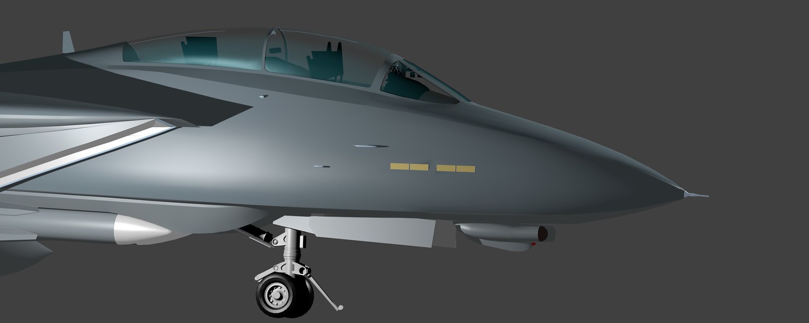
All good, I’ll for sure get back to you once I refine the front fuselage section. The tricky thing is as you pointed out stuff like the gunport, cooling ducts (NACA) and anti collision lights. If you have any input as to how to cleverly arrange the geometry in order to avoid the distortions when rendering it’d be much appreciated! The port side as you can see in the render is not really an issue but starboard is very messy :).
-
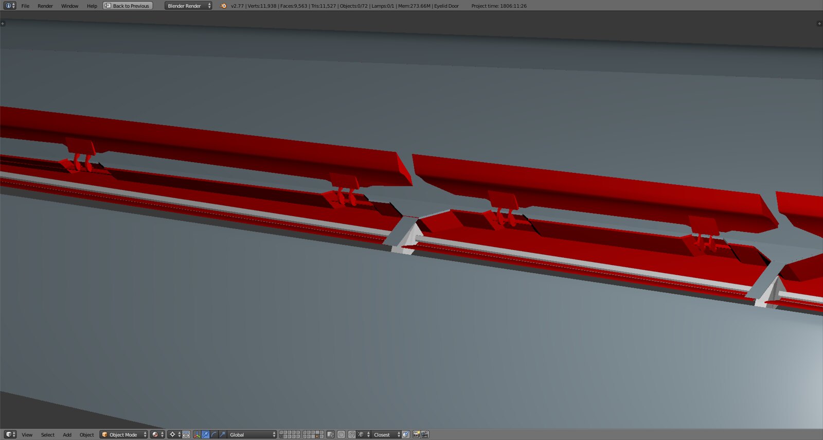
Finally getting to ‘recycle’ some of the parts I modeled a loooong while ago such as the spoiler hinges and some other parts. Flap hinges will follow once I got the eyebrow door separated.
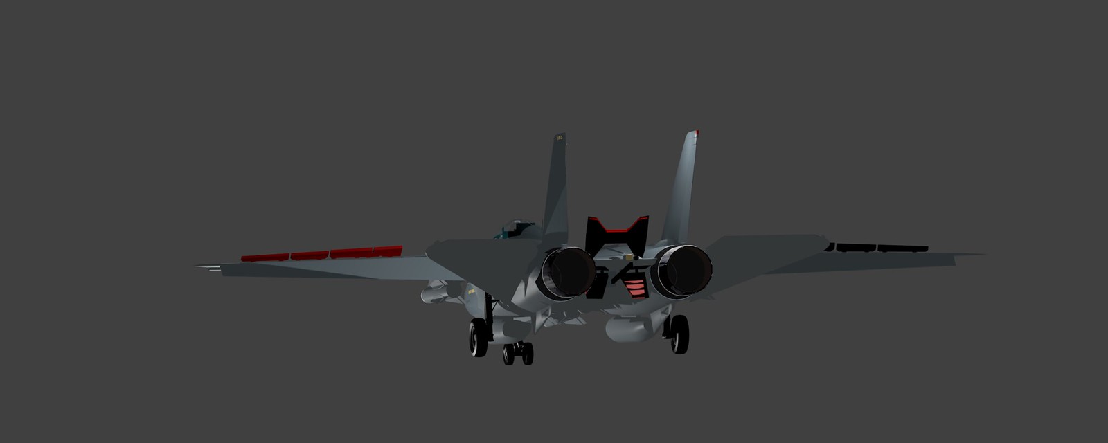
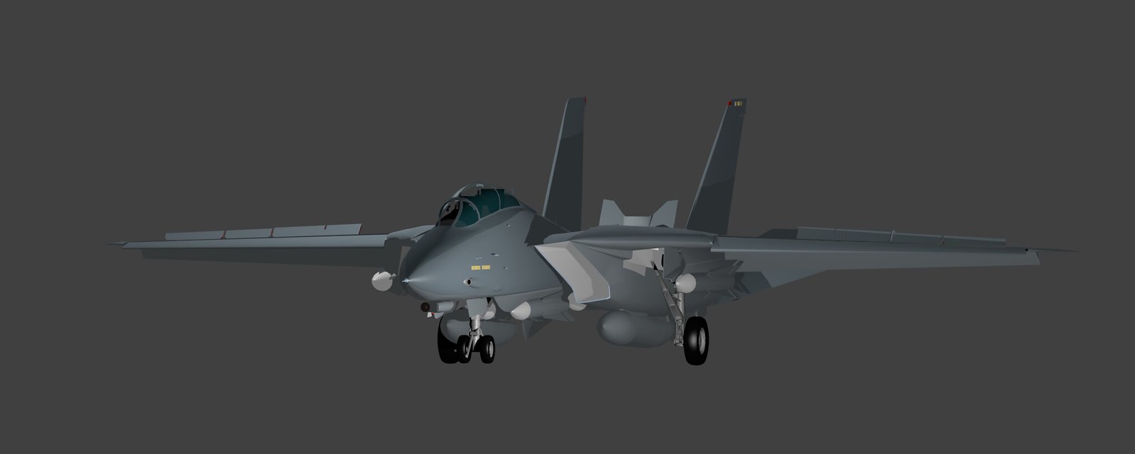
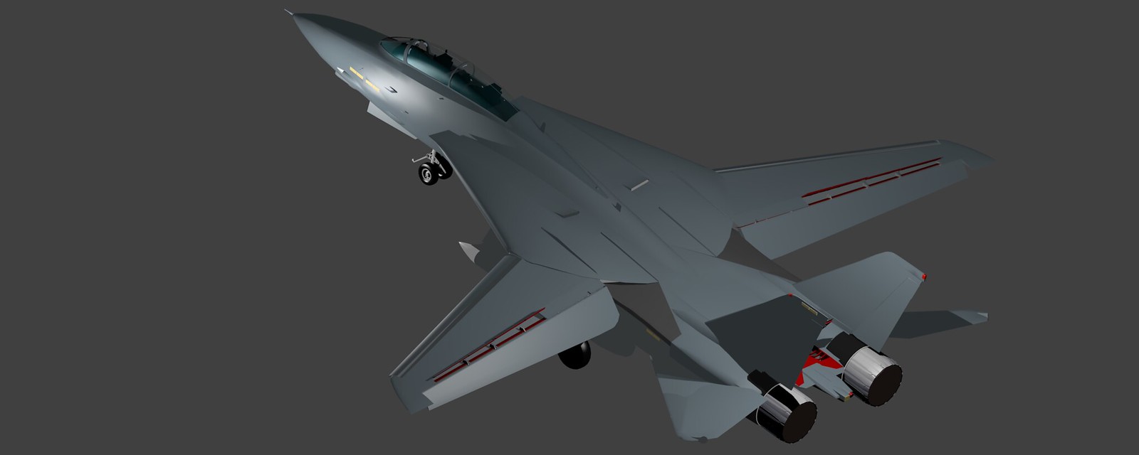
I modeled the wing in such a way that all three ‘Tomcat specialties’ will be possible for animation
-
the cove door, rotates up to facilitate airflow between main wing and flap when flaps are fully down, in that case the spoilers actually move down up to 4 degrees to meet the cove door and create a seamless surface between wing and flap
-
the eyebrow door, also a sealing surface, when flaps are up it rotates upward to meet the spoilers and fixed parts of the wing as to close the gap between the hard spoiler edge and the downward sloping forward flap area, when flaps deploy it rotates fully down to build the counterpart to the spoiler/cove door assembly and create a seamless surface along the forward flap edges
-
inside spoiler acting as airbrake, in RL when the airbrake is deployed spoilers 3 and 4 (inside) go up to their max 55deg position, therefore the spoilers are all independently movable but paired in terms of 3/4 and 1/2
Lots of details and fine tuning to do but now that I have the rotation limits set actually modeling as in smoothing out and arranging geometry is simply a question of time :D.
-
-
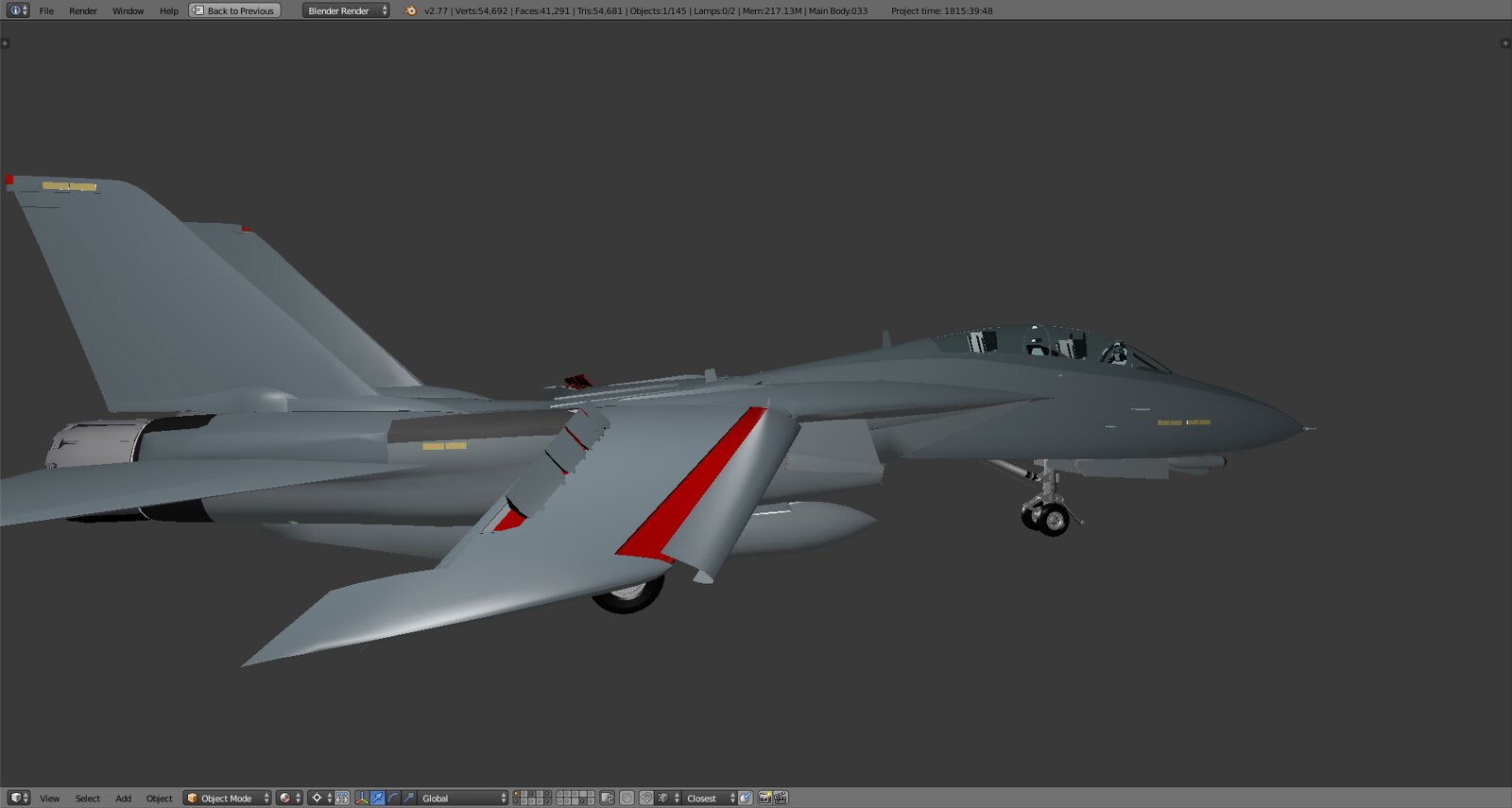
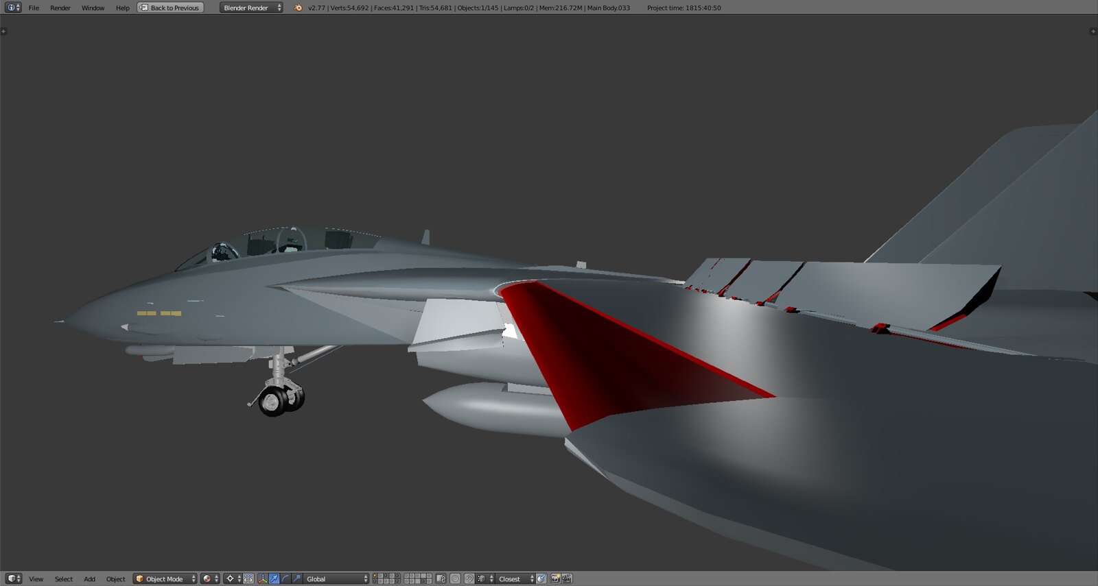
Last ones from the weekend rendering session…
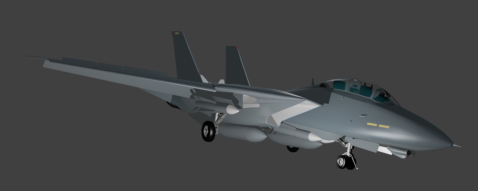
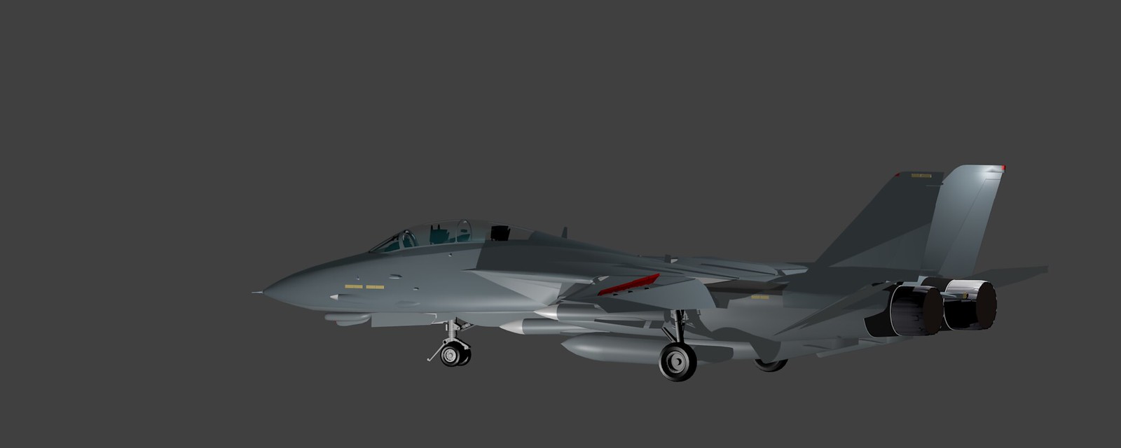
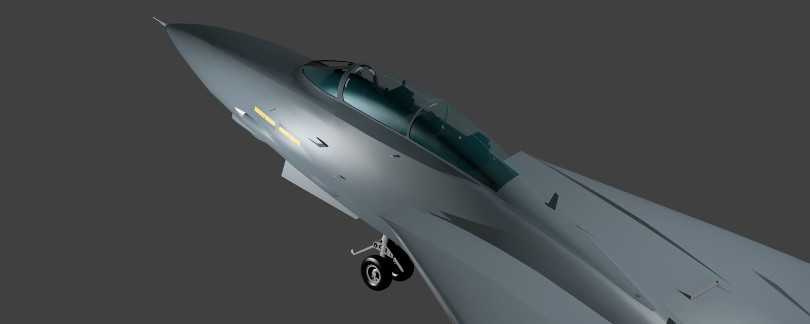
By the way in the last shot you can see the distortion that BeakerVBA mentioned created by an asymmetry along the y axis in the side of the front fuselage along the AC lights and gunports. Has been corrected but not yet rendered again.
-
A flap, well actually two flaps - aux and main. They mostly move together but not always.
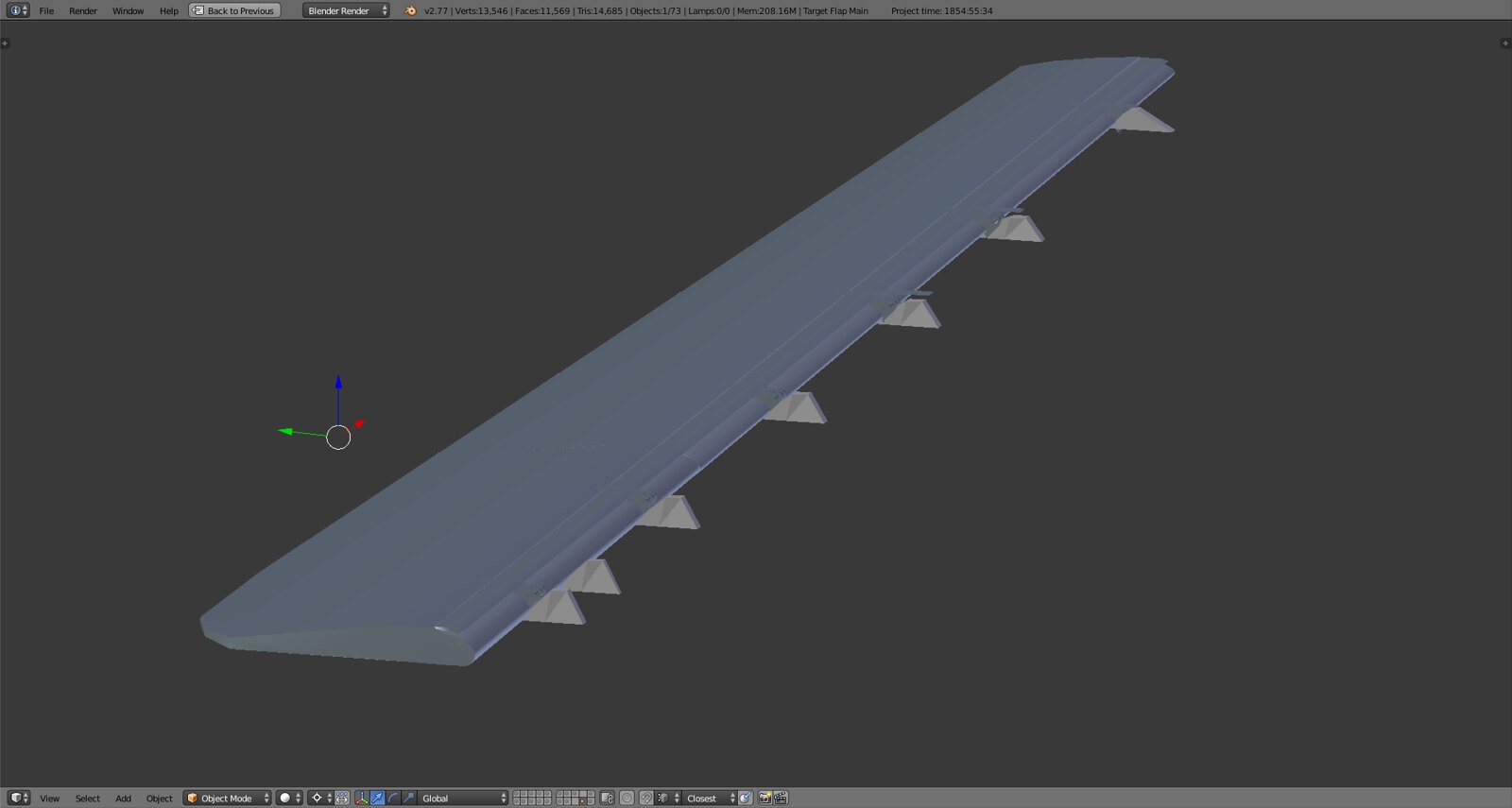
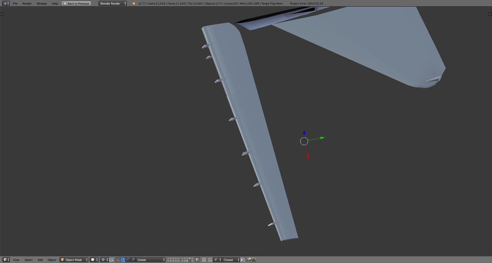
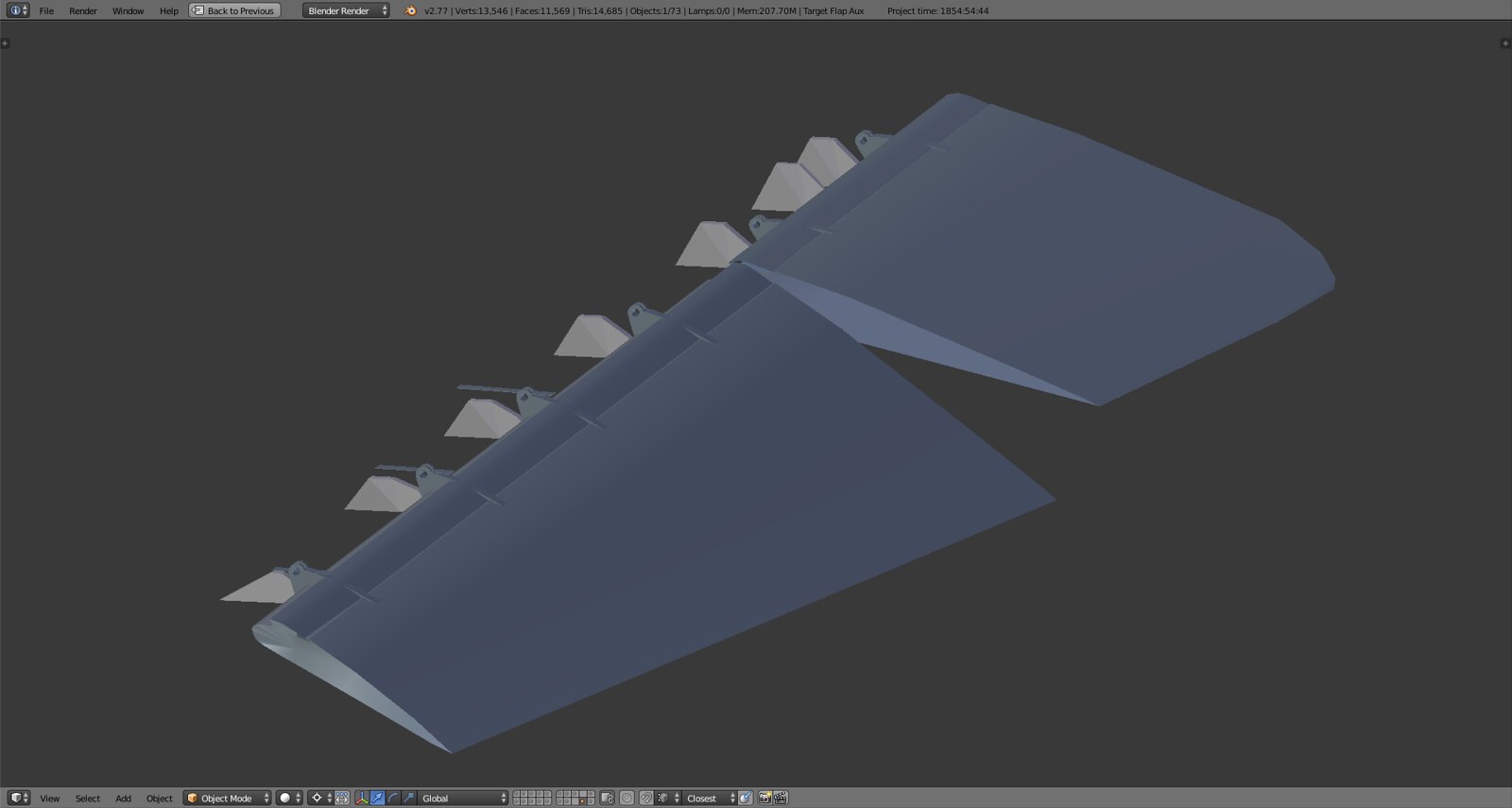
Above we now have two separate flaps, two separate eyebrow doors, flap hinges for the hydraulic actuators and the base attachment points. Alignment and complete geometry unfinished. I guess in the end I’ll have two merged flaps, separate objects for hinges, eyebrow doors and holding structures to keep tris count down.
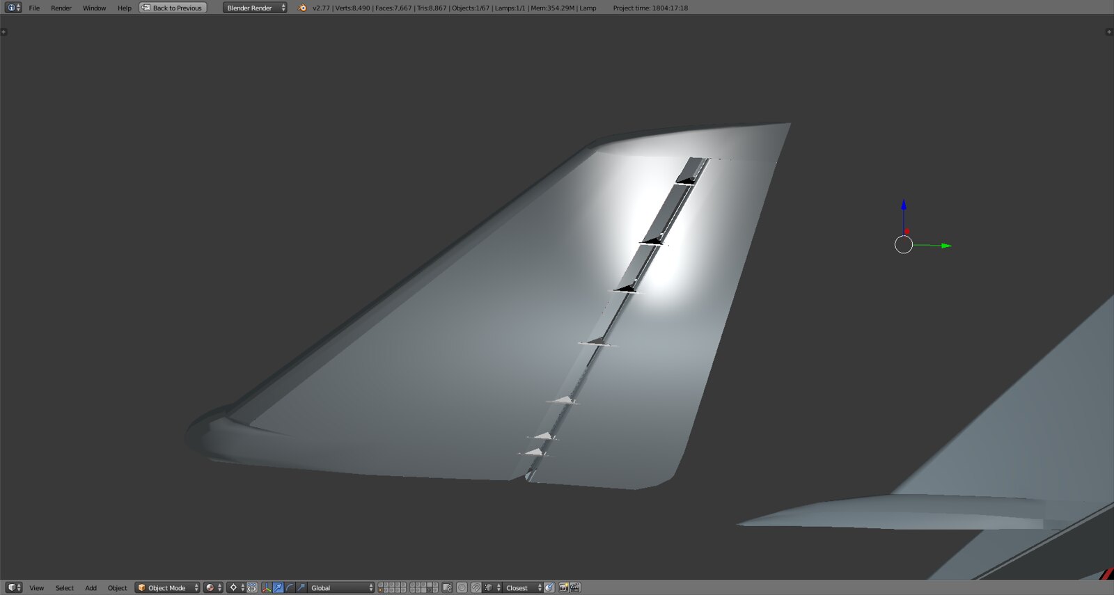
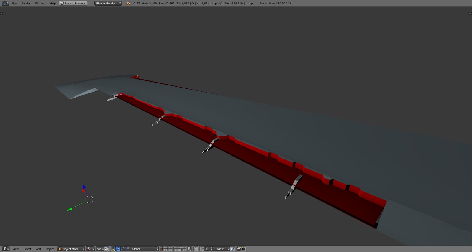
Main wing slat area adjusted to RL shape. I’ll add some minimal structure to the slat itself and the hinges to keep the balance between realistic look and minimum geometry added.
And corrected shape with accurate colors, the real paint scheme has a small grey stripe on top as to not have the ‘danger red’ shimmer through when the slat is fully retracted.
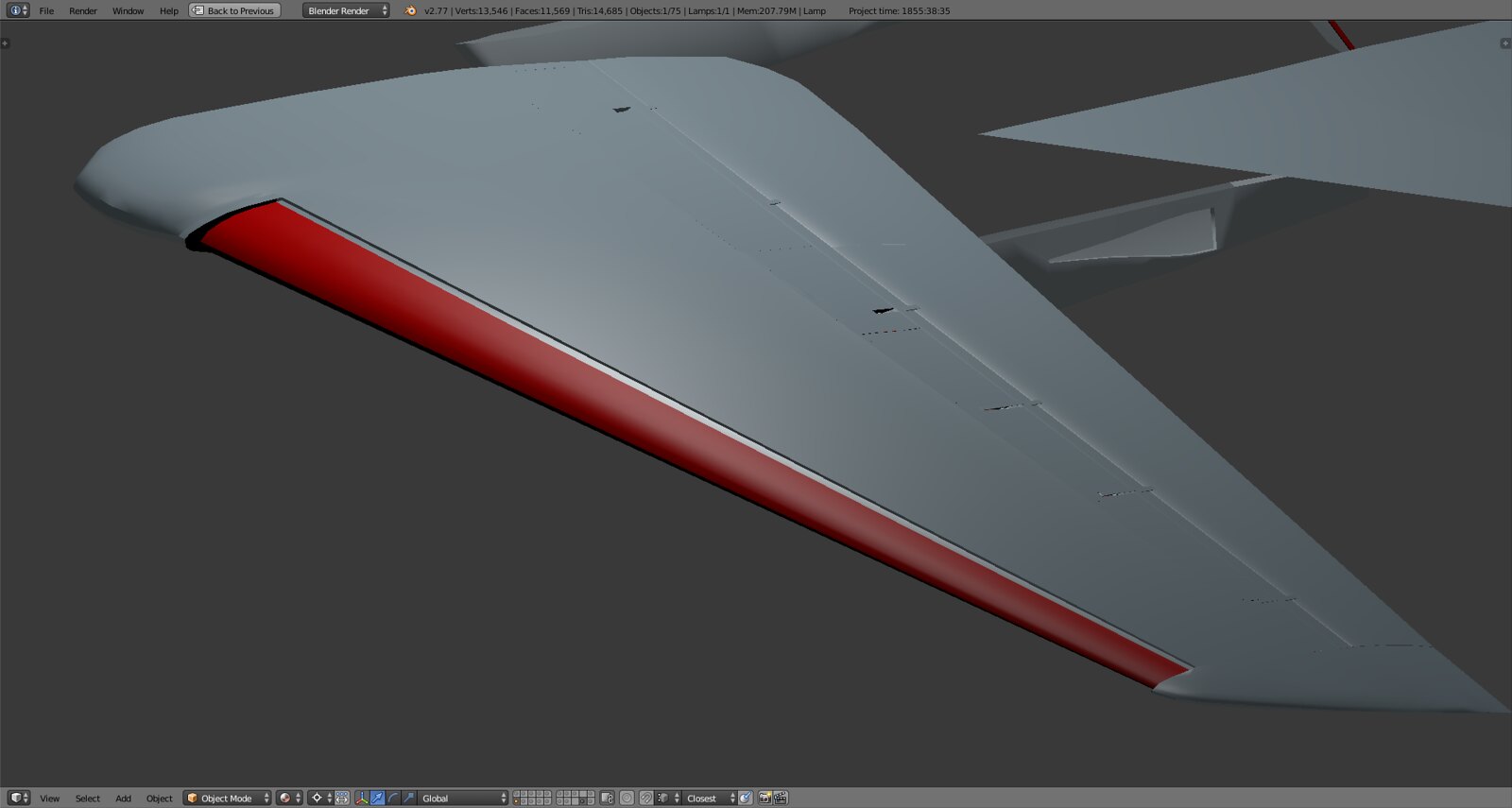
The correct animation of the slat will be postponed to 3ds because I’ll need one translation and one transformation DOF (as Pumpyhead has remarked like 30 pages back) in order to mimic the movement forward and down. Right now the slat is rotated which in RL it is not. In RL it rolls off a rail on circular hinges thereby moving it down and forward. This would be too complex to implement in Blender without using an armature which would be pointless.
-
Absolutelly

-
@SEG:
Absolutelly
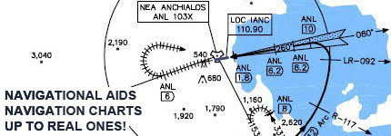
Believe me, that’s my favorite pic and probably most used. Hail to Thorsten at M.A.T.S.!
-
In case you would integrate full moving surfaces laws :
The two outboard flaps sections are the main flaps utilized during both modes of operation (10°). The inboard section (auxiliary flap) is commanded only during takeoff or landing.
The slats consist of two sections per wing moving at the same time.
For roll control below 57 deg, the F-14 uses spoilers in conjunction with its all-moving, swept tailplanes, which are operated differentially; above 57-deg sweep, the tailplanes operate alone.
For unswept, low-speed combat maneuvering (20° sweep), the outer 2 sections of trailing edge flaps can be deployed at 10 deg and the nearly full-span leading-edge slats are drooped to 8.5 deg.
Again and again thank’s for you Huuuuuuuge work -
@SEG:
In case you would integrate full moving surfaces laws :
The two outboard flaps sections…slats consist of two sections per wing…moving at the same time.
Again and again thank’s for you Huuuuuuuge workEverything you describe can be implemented except the systems overlay in terms of spoilers for example. AFAIK it would not be possible to assign a dual function to the inside spoilers for example. Acting in certain conditions along the envelope as spoilers and then as a fixed aux part of the airbrake when that is deployed. Apart from that it’s all possible including the dual flap depending on the conditions you mentioned. By the way the spoilers are operable throughout the entire wing sweep regime as they add roll control when wings are fully swept since the tailplanes cannot operate fully as you stated. Just saying they’re always active in some sort of capacity.
As far as the physically split parts of slats and flaps I’m aware of the construction BUT it would be unfeasible to model that. I have textures to give it a realistic look and you wouldn’t be able to see a mesh separation anyway as they always move at the same time.
Thanks for the detailed explanation!
-
stingray I believe we told you already… you are sick m8… :lol:
Don’t change your prescription… you are on the right direction… :lol:
So you are done already or more details need to go in before you switch to 3ds max and start Falcon working on this puppy?
Really are there any other details to go in? :lol:RESPECT man!!!
HOT LIST

System Specs:
i7-2600K @ 4.8 Ghz WaterCooled / 32GB Ram. 128GB SSD/1TB SSD / GTX1080Ti 11GB DDR5X / HOTAS COUGAR. TrackIR 4 / 3x24" Mon. (res:5760x1200) / Cougar MFD's / Wheel Pedals / Win 10 64 bit.

-
stingray I believe we told you already… you are sick m8… [emoji38]
Don’t change your prescription… you are on the right direction… [emoji38]
So you are done already or more details need to go in before you switch to 3ds max and start Falcon working on this puppy?
Really are there any other details to go in? [emoji38]RESPECT man!!!
Good questions, I guest at this point it’s a really short list:
- intake ramps and connection to air outlet
- mesh optimization
- separating and naming some objects (important for 3ds as that info is also imported)
- refueling probe and doors
- tail hook detail and assembly
- AC and position lights on the main wings
- crew steps and ladder
- RIO ejection seat rails
- simplistic actuators for all moving parts (landing gear doors, airbrake, flaps, etc)
- landing gear details and some simplification
The tex mapping can also be exported to 3ds not sure where I’ll do that yet.
Sent from my STV100-4 using Tapatalk
-
For the textures and materials to work on may I suggest substance painter…
It has a magnificent database to create the basic materials. Best I’ve seen for metals.
Also it’s magical for the wearing and dirty parts…U can paint on the 3d model no need to back and forth with Photoshop.
It has layers and everything needed.
Sure it ain’t free #cough# #cough# but it’s exceptional.
About texture mapping I don’t know if Blender uv mapping is compatible with 3ds max.
You can do a small separate part in blender and test it in 3ds max.
HOT LIST
System Specs:
i7-2600K @ 4.8 Ghz WaterCooled / 32GB Ram. 128GB SSD/1TB SSD / GTX1080Ti 11GB DDR5X / HOTAS COUGAR. TrackIR 4 / 3x24" Mon. (res:5760x1200) / Cougar MFD's / Wheel Pedals / Win 10 64 bit.
-
For the textures and materials to work on may I suggest substance painter…
It has a magnificent database to create the basic materials. Best I’ve seen for metals.
Also it’s magical for the wearing and dirty parts…U can paint on the 3d model no need to back and forth with Photoshop.
It has layers and everything needed.
Sure it ain’t free #cough# #cough# but it’s exceptional.
About texture mapping I don’t know if Blender uv mapping is compatible with 3ds max.
You can do a small separate part in blender and test it in 3ds max.
I actually have a painter like that (may even be substance painter) that works as the one you describe in which you ‘paint’ the material on the 3D surface in PS and it automates the tex mapping. Those programs are f***ing awesome!! Not sure how accessible or applicable they are here.
As for the Blender UV mapping I’ve tested it already and it transfers everything lossless if you apply some tricks when exporting from Blender.
The only thing that 3ds is really necessary for is the DOFs and material types for export to BMS AFAIK.
-
Acting in certain conditions along the envelope as spoilers and then as a fixed aux part of the airbrake when that is deployed.
This should be possible as well if you are talking about spoilers as airbrakes on landing. I believe it is DOF 7. I will have to check one of the heavies that have it (DC-10, E-3, E-8, KC-135).
-
This should be possible as well if you are talking about spoilers as airbrakes on landing. I believe it is DOF 7. I will have to check one of the heavies that have it (DC-10, E-3, E-8, KC-135).
Yes, the two inboard spoilers augment the speedbrakes but only below a certain airspeed and when wings are at 20deg sweep. In this situation the outboard spoilers are still available for pitch control while roll control is handled by tailplanes.
-
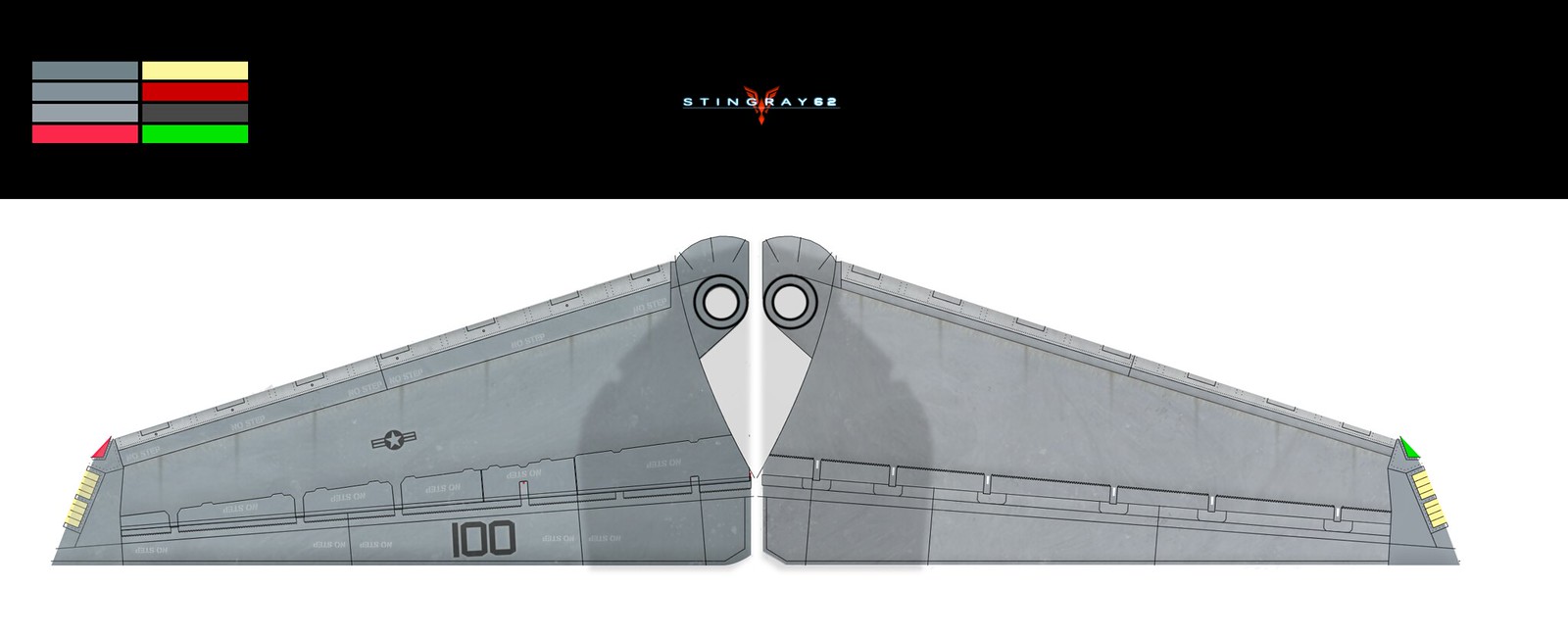
Someone asked for textures a while back. Here’s is a small selection of front fuselage, wings and stabs. All panel lines have been drawn based on all available information and all textures were created based on the real jet, not a specific model. So some adaptation will have to happen but if the model is close to RL it won’t be a big hassle once the model is unwrapped. The stab and wings clearly shows maximum weathering that you would expect out on sea while the front fuselage has only color, panels and some stencils.


-
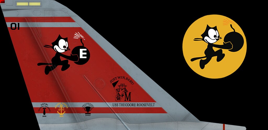
As long as there is my favorite, “VF-31 Tomcatters, AJ 105, BuNo 159619” during OIF 2005-2006, everything will be fine !
-
One of the few surviving airframes and on display in Florida. Nice choice!
No worries man I got you covered…
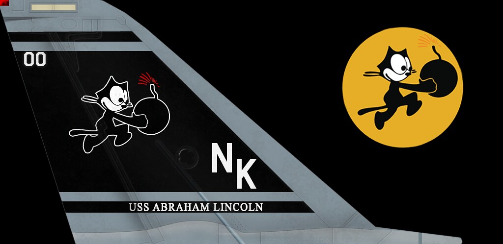
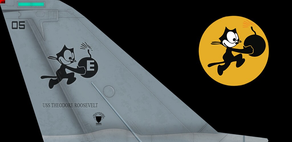


Probably my favorite tail ever next to Lo-Vis Jolly Rogers on the Bravo. The bluish tint makes the whole bird look incredible!! It’s no accident. Flying Pencil FTW!