WIP: F-14 B/D
-
That’s right. As a slight extension I might add that part of the issue is the lack of implementation in terms of the flaps. The flap is not one single part as can be seen here:
https://c5.staticflickr.com/9/8632/28319477060_5eaf1aa5be_z.jpg
Quote from NASA:
“Leading-edge slats and trailing-edge flaps are used to improve maneuverability at high subsonic speeds as well as to increase wing maximum lift coefficient at low speeds. The auxiliary flap shown in figure 11.32 is used only at low speeds to increase maximum lift. In normal operation, the maneuvering flaps, wing-sweep angle, and vane position are automatically controlled by a computer in accordance with a stored program that utilizes inputs from several measured flight parameters such as angle of attack, static and total pressures, and temperature.”
Without going into too much detail the main points are there is an automatic flap and slat retraction from takeoff and landing positions for airspeed greater than 225kts.
That being said the auxiliary flap only works when the wing is fully extended but manouver flaps (the main flap on the outside of the wings) and slats are deployed automatically by CADC/DFCS as a function of Mach number and AOA up until around Mach .85. Meaning even when the wing is not fully extended these control surfaces work and are deployed automatically by the system.
Specifically, if wing is aft of 50deg sweep the slat and flap (main and aux) are locked and remain fully retracted. The aux flap is locked and fully retraced aft of 22deg sweep. Between 21deg and 50deg the slats and main flap are deployed by system. In this regime the slat deploys up to 7deg and the main flap up to 10deg.
https://c7.staticflickr.com/9/8366/28319719190_6a8709e079_z.jpg
https://c1.staticflickr.com/9/8707/28497384392_df792ed076_z.jpg
On early F-14s the glove vane is incorporated into this logic but for the purpose of this discussion can be ignored as the vanes were dropped later on. Apparently the only people ever figuring out how to effectively use the glove vanes are the IRIAF pilots and tweakers.
FYI plenty of F-14A US squadrons used the glove vanes auto and manually up through the mid 80s. I think its an early Snort airshow vid on youtube that shows them being deployed (manually) during the max performance turn. They’re seen and used in the Final Countdown movie and Top Gun. Though they didn’t offer any real design benefit except at higher mach, they did reduce pressure on the tailplanes, possibly increasing pitch response when used manually. My guess is 90% of the time you witness them, its for show only.
-
FYI plenty of F-14A US squadrons used the glove vanes auto and manually up through the mid 80s. I think its an early Snort airshow vid on youtube that shows them being deployed (manually) during the max performance turn. They’re seen and used in the Final Countdown movie and Top Gun. Though they didn’t offer any real design benefit except at higher mach, they did reduce pressure on the tailplanes, possibly increasing pitch response when used manually. My guess is 90% of the time you witness them, its for show only.
Thanks Turkey. I still have our discussion regarding the vanes (you, mike metcalf and me) spreading over two pages in the other thread somewhere :). I still plan to compile all of the info into some sort of .pdf ‘collected info on the cat’ kinda document. Probably be done in 3-4 weeks

-
and only 14k triangles? wow you drawn every line and vertex manually?
Not sure what you mean. I usually draw one piece by hand and from there on out Blender has a beautiful set of key shortcuts to duplicate, flip, rotate, move, resize, etc objects so it’s mostly trying to model sth completely manually only once. For instance the hinge attachments you see on all struts and bars on the front and main landing gear is actually a piece taken from the spoiler hinges on the wings - it’s all the same only resized, skewed, tilted and so on. Not sure if that addresses your question. Of course something like the main strut link has to be modelled and took a good 2-3 hours because the part is mostly unique in shape and form.
The tris count of the landing gear excluding wheels is actually only around 4k. I have to figure out a way to reduce count on the wheels and rims. They’re currently modelled at max detail meaning even without smooth shading they look nearly perfect. That’s something with lots of room for optimization.
In case you made a joke and find 14k for the gear a lot I’d have to agree. If I left it at this LOD I’d end up with 25k for the landing gear leaving 5k for the rest :). That would bring the bird ‘all-in’ to 60k at least.
Things left to model excluding the landing gear:
-
airbrake inside and bottom part
-
arresting hook and assembly
-
beaver tail antennas
-
hydraulic actuators for the wings
-
AIM-54
-
refueling probe
-
cockpit
-
chinpod
-
some inside detail on the wing body and the landing gear compartments (simplistic stuff like adding some structural detail no hydraulic lines or anything like that)
Then I dare to say it’s ready for MAX.
-
-
Great job as always!
That model is a beauty to watch!
Pepe
Thanks mate. Good to know you’re still around!

One of the original Tomcat Tweakers of BMS everybody :)…
-
Awesome badge… want

-
Thanks mate. Good to know you’re still around!
https://c6.staticflickr.com/1/670/22491357933_75742befa6_n.jpg
One of the original Tomcat Tweakers of BMS everybody :)…
We need this cockpit… Damn the Tomcat is the most legendary jet fighter !
-
We need this cockpit… Damn the Tomcat is the most legendary jet fighter !
And with the howling sounds…
Still have those files on hand
")
PS: Having seen that old model in the video I suddenly realize how far this new one has already come. And here I am worrying about modeling hinges of landing gear shock absorbers…:D
-
And with the howling sounds…
Symphony of victory !
It was you who made the Tomcat for FF 5.5.5 ?
-
Symphony of victory !
It was you who made the Tomcat for FF 5.5.5 ?
No I only ever produced skins and they used one of my screenshots for the FF installer :D. I only seem to remember that ‘ZAGGY’ had something to do with the original model which is still the one used today in BMS. The original PSDs for that model which I and many others (also HRenner for the current BMS skins) used were created by one ‘Onesimus’ who since then has made quite the career:
http://www.onesimusnuernberger.com/
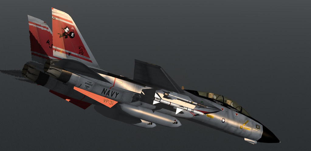
Thanks to Onesimus that old dog of a model is still going strong in 2016 (skin from 2014):
-
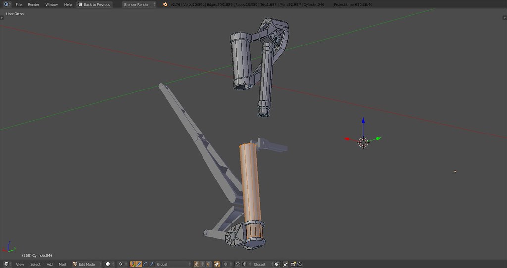
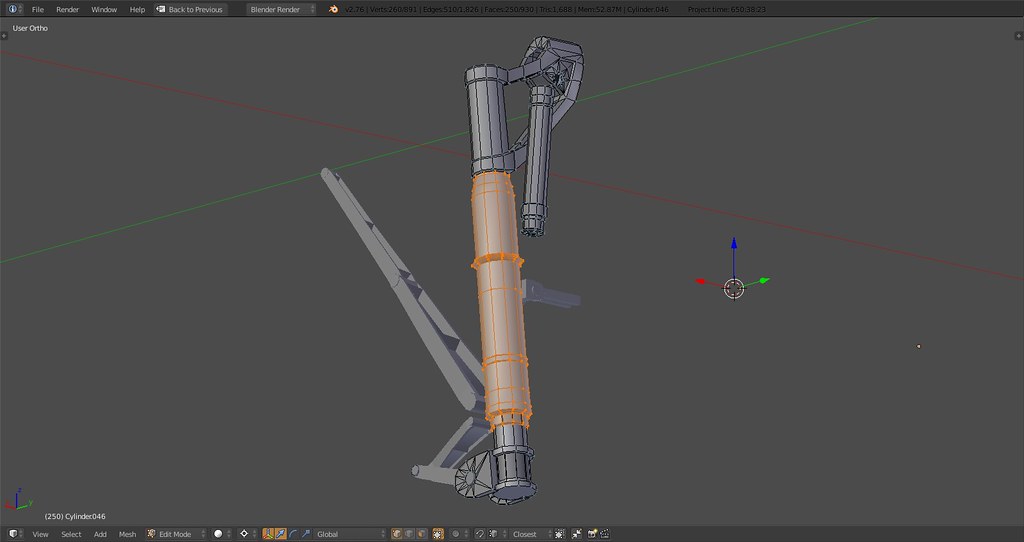
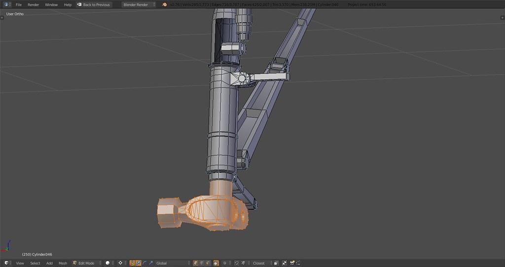
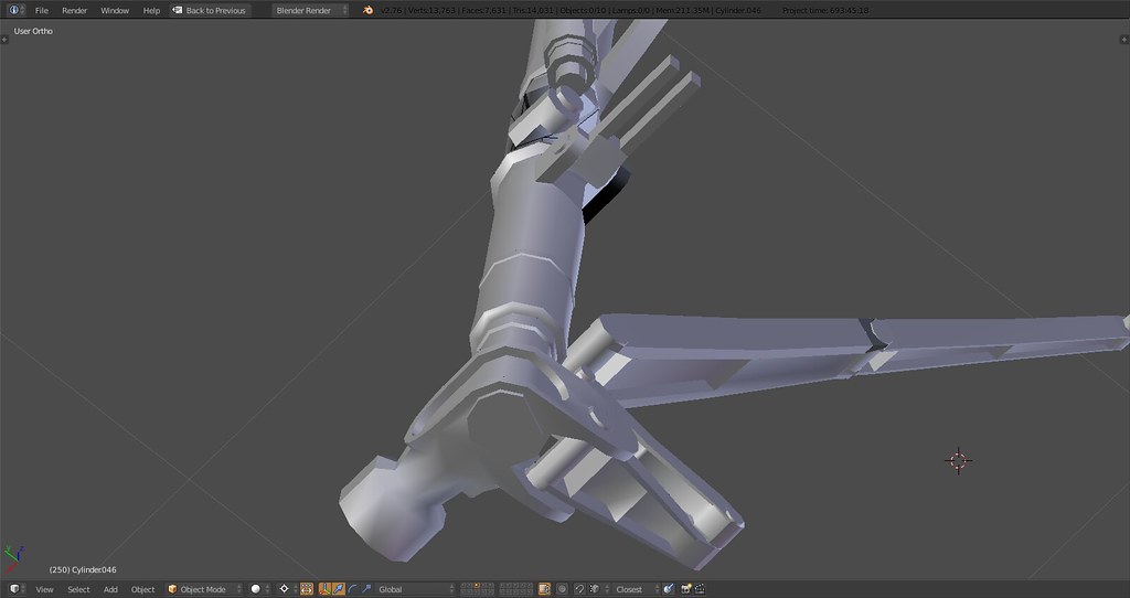
Update on MLG now including main strut, shock absorber, scissor link hinge, angled and rotated into default position:
Highlighted is the main strut lower part
Main strut upper part
-
errrr no I was not joking… As I read in a previous post you mentioned around 14k polys.
As I build my first ship My polys without the detail level I would want is above 20k.
And I was amazed of such a detail level in your model with only 14k and I thought I’m a dumbass lousy 3d modeler, with no good details and way high poly count at the same time.Anyway your model is super and I admire your patience and time on it… It will be an honor and a real joy to fly next to it some time… not in… from outside you can enjoy all it’s glory.
F-14 and Su-27 where my first child time posters cut out from magazines… I also have the Miramar TOPGUN publication with fabulous photos of her…
-
Looking all this progress makes me very proud of your work and very optimistic for the future of F-14 in BMS!! Keep up the good work! Thank you!
-
errrr no I was not joking… As I read in a previous post you mentioned around 14k polys.
As I build my first ship My polys without the detail level I would want is above 20k.
And I was amazed of such a detail level in your model with only 14k and I thought I’m a dumbass lousy 3d modeler, with no good details and way high poly count at the same time.Well to clarify the landing gear ONLY is at 14k. The model without the landing gear and wings is currently at 19k. The wings stand at 15k. So there’s only around 20k tris to shred
Realistically speaking it’ll be possible to land below 40k without compromising on proportions/desired detail on all objects including cockpit, landing gear, wings, surfaces, etc.
Possible below 30k? I’ll try but I doubt it, this aircraft is pretty much double the size of an F-16 in terms of area and easily has twice as many moving surfaces if not more.
-
Well maybe you should compare it with the F-18 model?
I believe those 2 are closer than an F-16.But with my way low experience it will be very difficult to reach such levels with optimization afterwards.
If you have flat surfaces ok but your model is the mother of all sexy curves ever existed… I really hope you’ll get the results you anticipate. Personally I don’t mind for some extra polys for my system as long as there are LOD levels. With Jan’s F-16 I had no problems at all. The thing is if the BMS guys will adopt it to an official setup and why not integrate it alike the F-18.HOT LIST

System Specs:
i7-2600K @ 4.8 Ghz WaterCooled / 32GB Ram. 128GB SSD/1TB SSD / GTX1080Ti 11GB DDR5X / HOTAS COUGAR. TrackIR 4 / 3x24" Mon. (res:5760x1200) / Cougar MFD's / Wheel Pedals / Win 10 64 bit.

-
You said it, it’s about doing it according to BMS specs with the goal of having it implemented. Also keeping in mind that everything is aimed at maximum usability and applicability which is the reason for the poly limit in the first place which I totally am in line with.
In terms of comparison my benchmark is actually WaveyDave’s Tornado as it is a twin engine, swing wing fighter of comparable dimensions and he put together a smooth, beautiful and highly optimized model with lots of details and high degree of immersion and that all-in below 30k.
I don’t expect to have the skill or experience to make that happen here but I’ll try.
-
Go ahead, I think that you can inside the proper limits…

Nikos. -
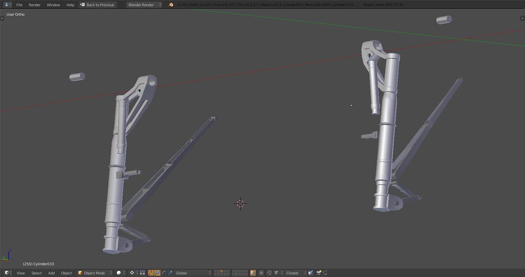
Got a little carried away with authenticity on the MLG, we might just get ourselves the most authentic landing gear on a virtual Tomcat yet without blowing the tris count
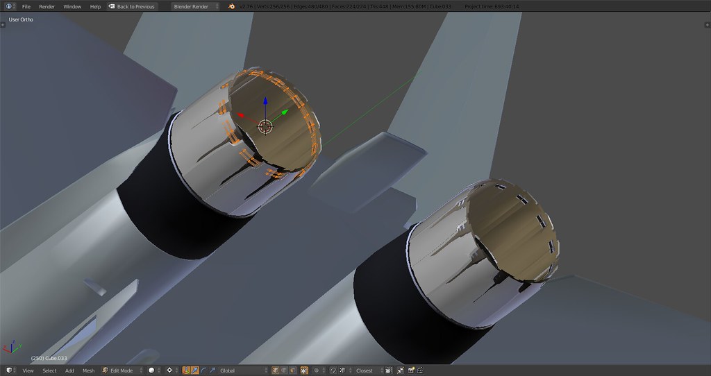
That being said I needed some distraction from the dampers, hinges and shock absorbers so I spent some time researching how people model engine nozzles and tried it myself…

Wicked eh?
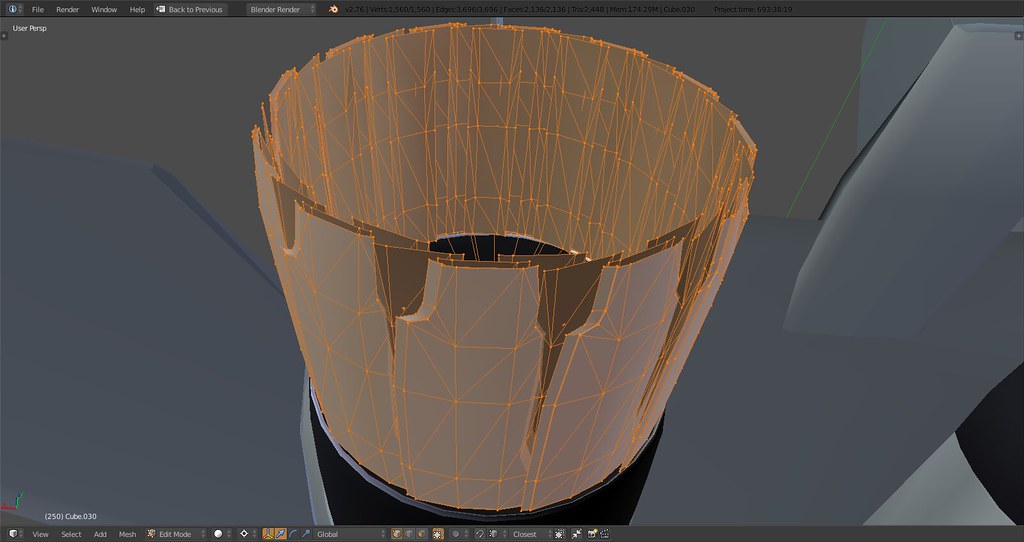
I modeled one plate, later added the extrusion on one of the sides and then duplicated part of the inside and added two more layers to get the desired effect.

Those rings will probably later be integrated into the exhaust nozzle plates on the inside…
Close up
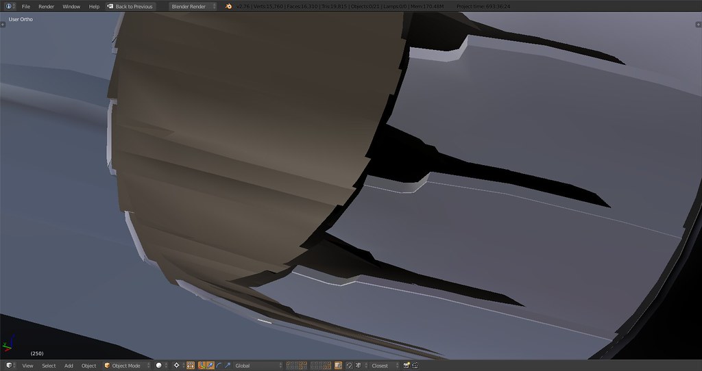
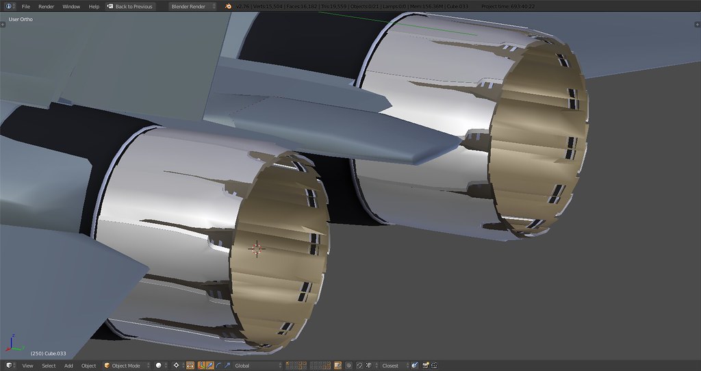
Basically I did one nozzle with all plates and details and then connected the backframe vertices to the center point of the engine bay, then duplicate and rotate the other 11 nozzles around that point. Probably did that about 20 times following all the corrections
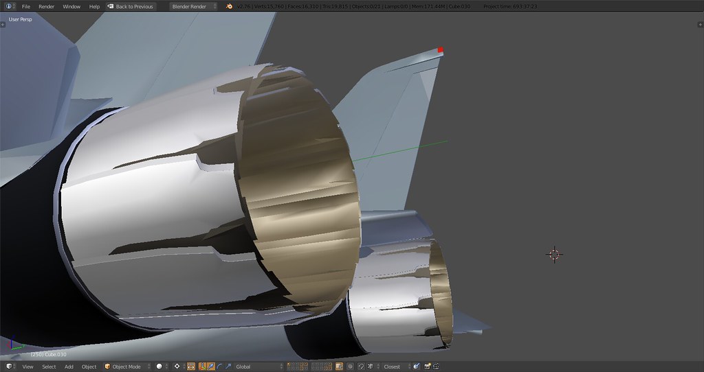
GE, Baby.
-
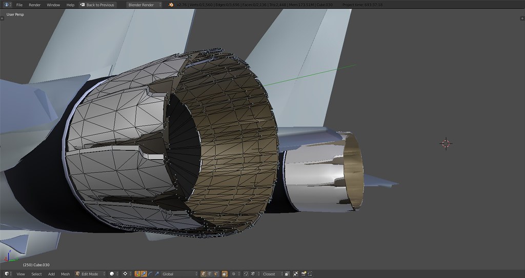
There’s actually only two inside plates I just realized whilst looking at my books. One directly below the outside nozzle and one with slight indents next to it, multiplied by 12 and rotated around it should then look like a tightly sealed inner outlet and slightly seperated outside nozzles. Correction coming up…even though I love the convoluted look of that plate mayhem the way it is now.
-
Really impressive :bowd:
There’s even the “not very well-known blocking T” on the main gear…. As much to say concerning these GE F110’s nozzles -
@SEG:
Really impressive :bowd:
There’s even the “not very well-known blocking T” on the main gear…. As much to say concerning these GE F110’s nozzlesThere is, I mentioned that a couple pages back but no one seemed to notice :D. The corresponding ‘hole’ in the fuselage will be there as well.