WIP: F-14 B/D
-
While browsing through my archive I found this and have to repost…probably single most impressive F-14 AFM comment in the history of the internet:
Originally Posted by molnibalage

No. Ps tells you the whole story. This is why so amazing the E-M Theory by John Boyd and Tom Chrsite. It was used illustrating AC dogfight capabilites. In the same case where an AC have bigger Ps that is the better AC in that case. End of the story.LOL

Dude, Boyd theory is just one way of looking at things. It’s by no means the only one or the best at that. It has it’s advantages for sure, but to quote another authority on ACM (one with more aerial kills then Boyd ever had), “the energy advantage determines when will the engagement start, the angles advantage determines how it will end”.Now, as to why specific excess power isn’t the whole story and with a concrete example of the F-14A. It is documented in video materials and photography that during air shows the F-14A was constantly being able to do a full 360 at minimum turning radius of about 1000ft without losing air speed in about 20 second. That is a circle the length of about 6300ft. The sustained turning rate in these examples is about 18deg/s. Doing a 6300ft circle in 20 seconds translates to about 315ft per second or about 185-190 nautical miles per hour (knots) air speed. Performing this at airshow means this is practically at sea level wish would mean a mach number of about 0.28. Now take a look at he Ps values around mach 0.3. Based on Ps alone, the F-14A should be able to pull no more then 10 or 11deg/s at best. Let’s presume that the aircraft performing this aerobatics at airshows are probably running an extremely light configuration with only 10% internal fuel. The empty weight of an F-14 is 43,735 lbs. Maximum internal fuel capacity is 16,200 lb. If our chart describes a clean AC with a 100% fuel tank that would account for a 59935lbs Tomcat. The airshow Tomcat would be 45355lbs in comparison. 75-76% the total mass. Are you trying to tell me that a 25% decrease in mass results in 44% increase in sustained turning performance??? There is something not accounted for here mate, something that Ps alone can not quantify. That’s where the lift coefficients and induced drag come to play. At the lower edge of the envelope. For the F-14 that’s between mach 0.2 and mach 0.7.
You already know the higher wing aspect gives the F-14 decrease in induced drag twice as large compared to the F-15. The NACA 64A209.65 mod 64A208.91 mod airfoil has a similar lift coefficient at the tip to the NACA 64A006.6 NACA 64A203 (used on the F-15), but unlike the F-15 which provides no effective lift at the root, the F-14’s has lift coefficient of 0.2. Add the 40% increase in lift experienced when going from 16 to 25 deg AoA a as a result of the body-glove vortex flow lift…… Do you need more evidence?As for what did i modify on my test chart, well it was an F-4E STR chart which i tweaked with the F-14A Ps curve and added the 20% increase in STR (of the F-14 VS F-4E) as documented by NASA. It still doesn’t tell the whole picture as the F-14 and the F-4 have very different aerodynamic properties especially on the left side of the diagram.
- Mike Metcalf
Lovin’ it

-
Oh man,
I should work at my cockpit to come to an end, but the link you mentioned has excited me so much, I couldn’t stop reading :D.
Yeah, lot of Tomcat-Lovers here, I’m not the only one. Very detailed informations in those threads, but not so easy to understand all the techincal infos, if English isn’t your native language.
Are there any real or retired pilots in this forum, who had flown this bird? Could help alot with the model. Don’t know if flightsimulation is so interesting, if you had flown the real fighters, but maybe there are some ex-pilots in this forum. I’m to new at this forum to know all its members.
-
On facebook, the famous Dave “Bio” Baranek can answer to questions.

Also, I’m member of this group, there is a lot of crew chief, ground crew, and former Tomcat’s pilots here. Join the group !
")
https://www.facebook.com/groups/53360498213/ -
SPOILER ALERT (pun intended :))
Some angles
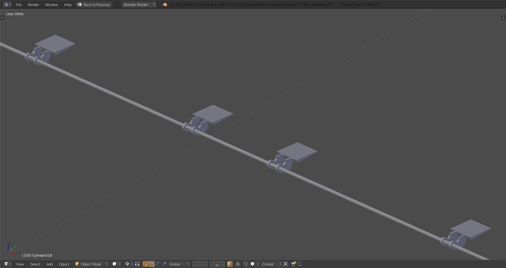
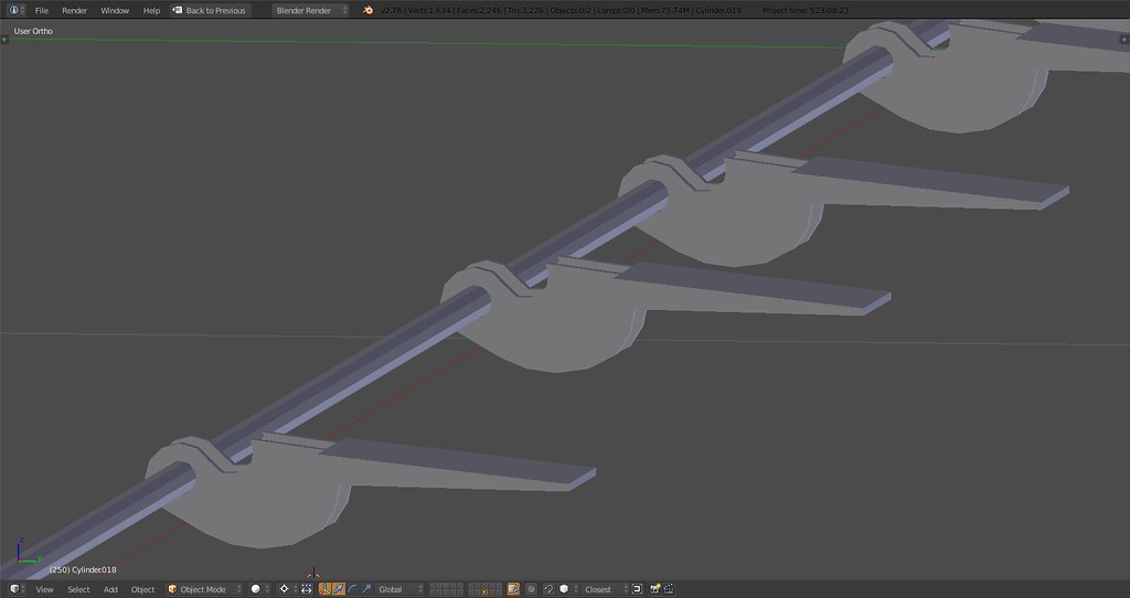
Spoiler hinges with shaft:
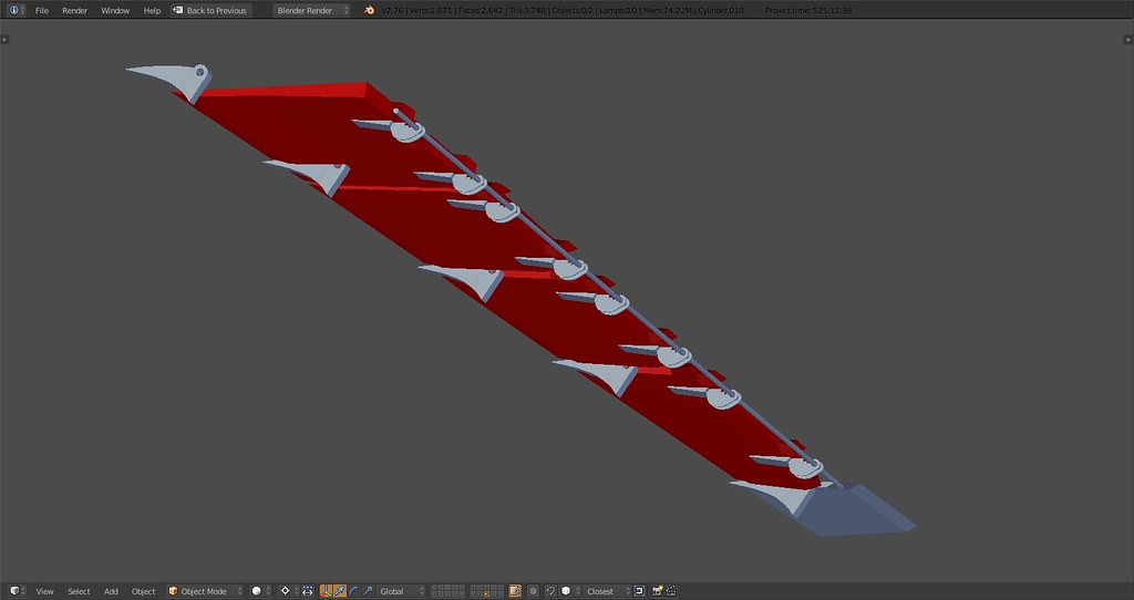
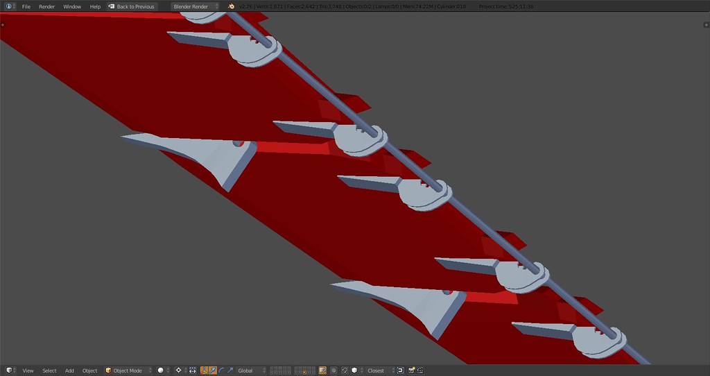
Details:
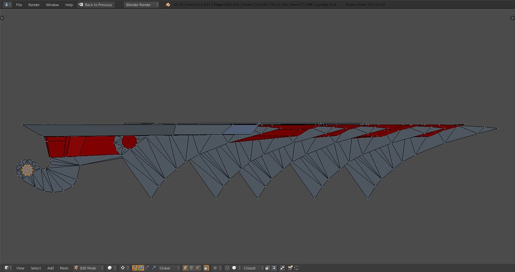
Spoilers and their assembly hinges rotate on the shaft that will barely be visible but is important for rigging.
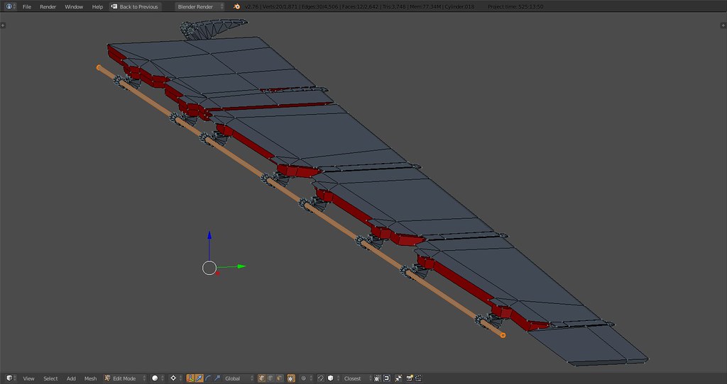
Hinge detail
To move this development away from the wing was necessary to ensure symmetry and make the alignment process easier. Spoilers will get some more detail but not much as the whole assembly including the flap will take up around 3000 tris easily - then again this is the most important element of the entire aircraft (the wing that is).
You can see the flap hinges there as well partly covered by movable plates partly visible through the spoiler gap. There are 5 hinges in total. Flap and the lower cove door which swings up when the flap is retracted will follow…
-
On facebook, the famous Dave “Bio” Baranek can answer to questions.
Also, I’m member of this group, there is a lot of crew chief, ground crew, and former Tomcat’s pilots here. Join the group !
https://www.facebook.com/groups/53360498213/Now I’m a member too (hope so must wait for the confirmation). Thank’s for the advice!
Sorry stingray, don’t want to fly off on the tangent. I will shutdown now :D.
P.S:
Unbelievable how detailed and complex your design of the aircraft is. Couldn’t wait to fly it. O.k. still have a lot to do with the pit. I look forward to the maiden flight.
Originaly I want to use the Huey and as background music “Green River” from CCR. Maybe it will be the Tomcat and the Topgun theme :mrgreen:
-
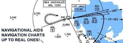
FLAPS
Since the wings don’t get any easier or simpler following the spoilers I used the motivation and carried right onto the flap assembly. This includes working cove- and eyebrow door. Slat will follow soon but is a bit tricky since it doesn’t rotate on a shaft but is ‘rolled out’ using a hinge rolling over a cog. Clearly something that has to be animated and cannot be rotated in 2D.
Full flap assembly all at zero deg:

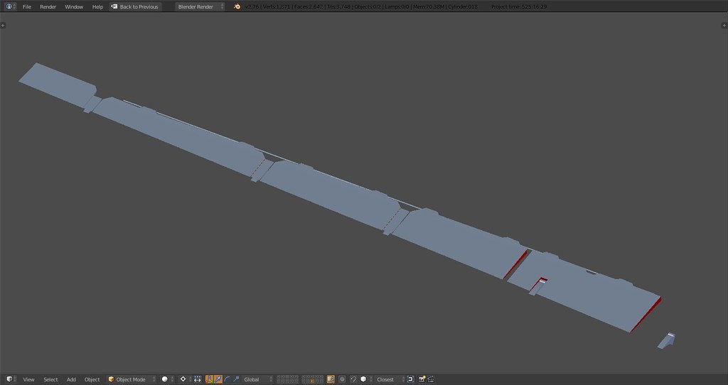
Bottom side, hinges visible through the various parts of the cove door:

Flap up at zero, eyebrow door at default position. The eyebrow door seals the gap between the spoiler edges and the downward slope of the flap when it’s fully retracted:

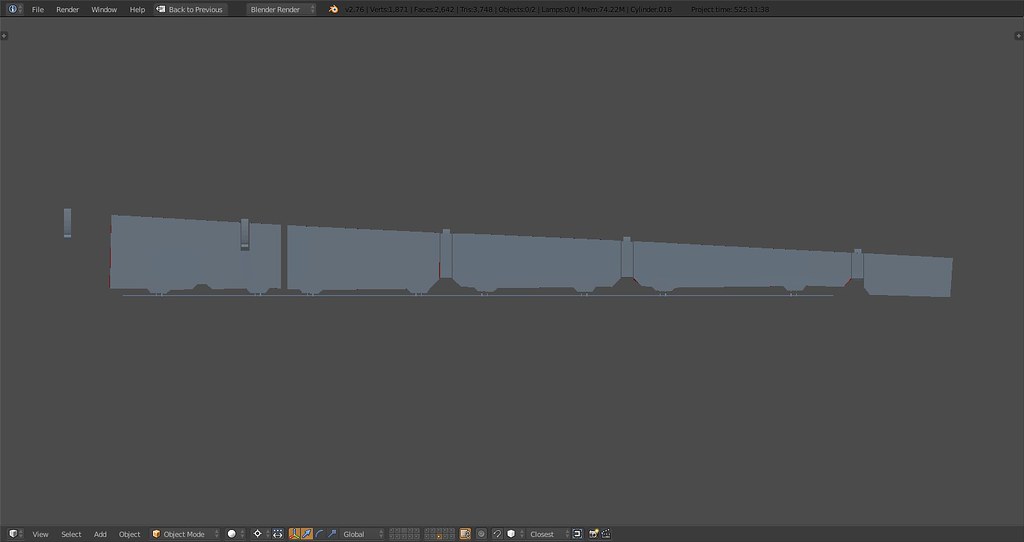
Flap maneuver positions (0-10deg), eyebrow door is up filling the gap, cove door still open:

Flap down (10-35deg), eyebrow door closed, cove door closed:

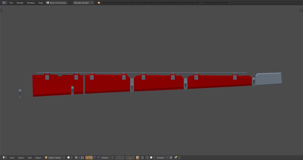
The doors, flap hinges and flap shaft in detail:


Oh and if anyone is wondering the topside hinges are for the hydraulic actuators that push the flap down. I’m actually not 100% certain yet if the flap ‘only’ rotates or also moves back with the entire assembly thereby moving along two axis down and back. What is for sure is that the flap rotates around the axis you see above.
-
Don’t forget wing flex.
")
-
Don’t forget wing flex.
Care to elaborate on that Pumpy? First off I didn’t know it was supported so great to hear it. Second how would that be modeled visually? Would it also apply to the tails? I remember many times seeing the stabs start to shake during high-g maneuvers.
For now I’m still busy with aligning the different parts of the wing and finalizing flap and spoilers including hinge points and some hydraulics.
-
This should give you an idea:
-
Flutter and Wing flex DOF’s exist in 3ds MAX Falcon Exporter F4DOF Helper.
How they work and how to setup… is a good question…
HOT LIST

System Specs:
i7-2600K @ 4.8 Ghz WaterCooled / 32GB Ram. 2TB SSD/1TB SSD / 20TB HDD Total / GTX1080Ti 11GB DDR5X / HOTAS COUGAR. TrackIR 4 / 3x24" Mon. (res:5760x1200) / Cougar MFD's / Wheel Pedals / Win 10 64 bit.

-
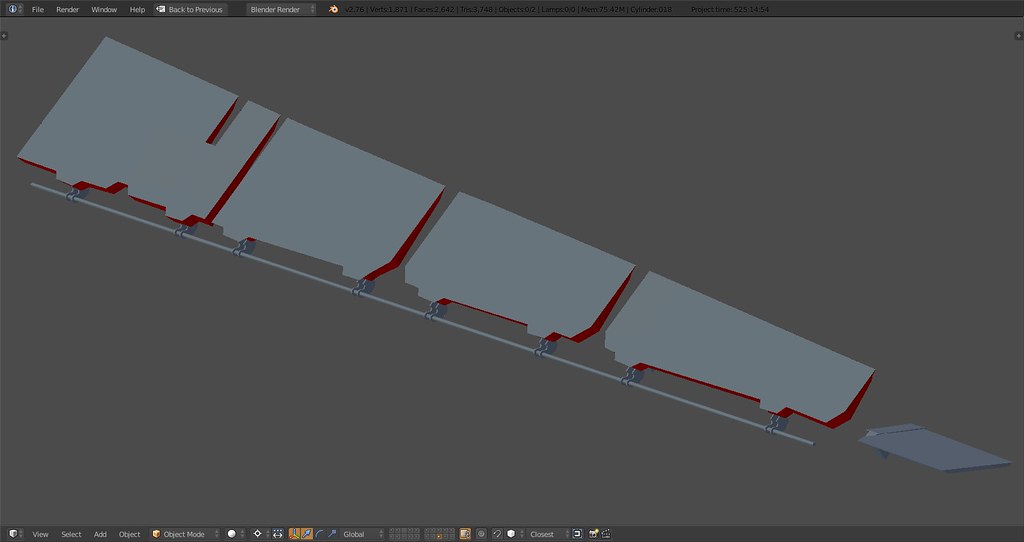
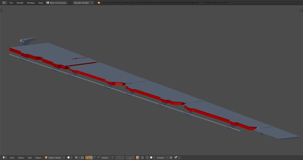
Some updates about the wings. After playing around with the cove door, eyebrow door and spoilers I basically had to redesign and relocate almost all vertices of these objects. Upside is they now fit and work together nicely and the shape resembles real life more. Not because I’m so obsessed about the details but out of necessity so the parts have freedom of movement and work together.
Flap hinge detail, it’s the inner hinge. It doesn’t have a cover and sits a bit lower than the others.

Hinge number two sits even lower and is smaller than the others. When retracted it is unvisible under the fixed part of the spoiler assembly. The cove door is split at that hinge.

Center hinge is one of three that has a sliding top cover attached to the assembly of the wing/flap. It rests on the hinge top and moves accordingly.

Hinge #3, uncovered hence the gap in the spoiler

Zoomed out:

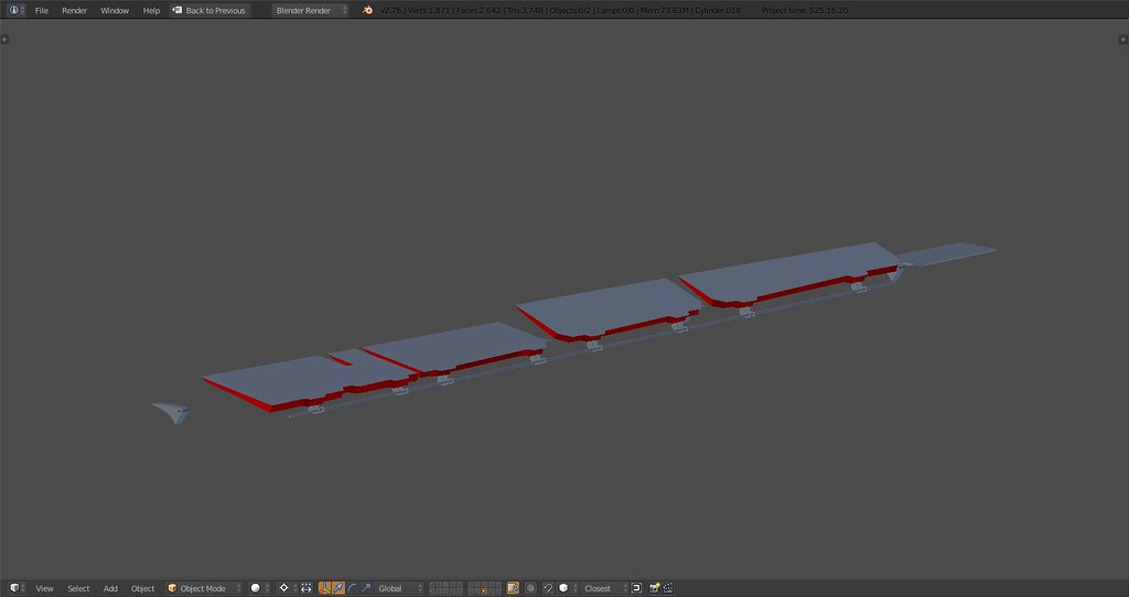
Viewed from below with flap hidden. You can see the closed cove door meeting the spoiler assembly. Almost invisible but modelled: The 4 moving spoilers, according to the F-14D NATOPS flight manual, move down 4 degrees to meet the cove door when the flap goes down beyond 25 degrees. The outer fixed parts of the spoiler assembly have matching shape:

And full view with spoilers 3 and 4 in upright ‘airbrake’ landing configuration:

Things left to do:
-
split flap into main and auxiliary part
-
adapt wing body and slat
-
integrate eyebrow door into flaps
Will post some more renders and detailed ‘drawings’ in the coming days…

Total tris for the complete wings: 14.800. Yeah, a lot. Expected that. Aiming for below 10K when finished. The wings will make up more than 40% of all tris once it’s done like I said before.
Moving surfaces, Baby.
-
-
Auxiliary flap with separate eyebrow door and adjusted edge of the fixed inside spoiler:


Question for you guys, any idea how I can align my axis view to the rotation axis of the spoilers in blender?

Currently the x axis is aligned to the rotation axis of the flap as can be seen here:

-
Nice steps ahead!!! Keep on this baby.
Nikos. -
L A N T I R N poddage


Delta cat, Baby.
Forgot to mention, I modelled the weapon pylons. Bottom part is the exchangeable separate object depending on loadout. AIM54 pylon and extension for AIM 9 and some details will follow.
-
Nice going!
However, in case you don’t know, Pods are now loadable just like any other weapons.
This means it should not be part of the model anymore.Gr Falcas
http://www.weapondeliveryplanner.nl
WDP 3.7.24.232, MC 0.5.26.746
WC 1.5.0.25, AIC 6.8.17, Set HUD only 1.6
I7-9700K, 32GB, RTX 2070 8GB, Win10-64bit, Full cockpit running BMS MFDs and RWR, MFDE for Instruments, AIC, FCC-3
-
Excellent work! You know Grumman is hiring!!!
@stingray_SIX_TWO:L A N T I R N poddage
https://c8.staticflickr.com/9/8624/28391540575_527d9b3f03_b.jpg
https://c2.staticflickr.com/9/8647/28312608001_e363a521c6_b.jpg
https://c4.staticflickr.com/9/8853/28391540715_dcb33cb593_b.jpg
https://c8.staticflickr.com/9/8572/28312608231_85889912a0_b.jpg
Delta cat, Baby.
-
Second how would that be modeled visually?
See the videos I posted. Basically, you have to cut the wing into sections adding a rotate DOF (25 & 26 for Left and Right wings) to each section. The F-16 wing has 3 sections affected by 3 DOF’s. The flutter is dependent upon the FM as well as other factors. The only control you have over the DOF is the amount of DOF movement using the Multiplier.
Be aware that everything on the wings including slots and the buffet DOFs on the slots and any LEF’s and TEF’s, etc… need to be under each flutter DOF section. It can get rather messy when cutting TEF’s and LEF’s, but the result is worthwhile IMO.
Would it also apply to the tails?
I suppose one could add the same to the tails.
-
Nice going!
However, in case you don’t know, Pods are now loadable just like any other weapons.
This means it should not be part of the model anymore.Gr Falcas
Thanks. I actually thought it was loadable all along :). I know of the Lantirn pod in BMS and that it’s shared between different ACs. I actually made some Tomcat specific skins for that pod a while ago.
Anyway, the plan here is to model all F-14 B/D specific objects including the pod and the AIM-54. Will not model the Sparrow/Sidewinder/Amraam obviously. What will be used in BMS in the end and to what extent/level of detail remains to be seen.
-
See the videos I posted. Basically, you have to cut the wing into sections adding a rotate DOF (25 & 26 for Left and Right wings) to each section. The F-16 wing has 3 sections affected by 3 DOF’s. The flutter is dependent upon the FM as well as other factors. The only control you have over the DOF is the amount of DOF movement using the Multiplier.
Be aware that everything on the wings including slots and the buffet DOFs on the slots and any LEF’s and TEF’s, etc… need to be under each flutter DOF section. It can get rather messy when cutting TEF’s and LEF’s, but the result is worthwhile IMO.
I suppose one could add the same to the tails.
Thanks for the explanation. Sounds good. Will deal with that once it’s imported in Max. Very interesting functionality visually and aerodynamically especially in combination with an accurate AFM and vapor!!
-
Anyway, the plan here is to model all F-14 B/D specific objects including the pod and the AIM-54. Will not model the Sparrow/Sidewinder/Amraam obviously. What will be used in BMS in the end and to what extent/level of detail remains to be seen.
So we’re not only getting an F-14 Model, we’re getting all the Tools of the Trade for the Tomcat as well? Awesome!