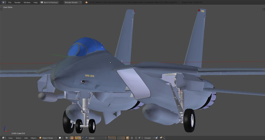
WIP: F-14 B/D
-
@SEG:
Really impressive :bowd:
There’s even the “not very well-known blocking T” on the main gear…. As much to say concerning these GE F110’s nozzles
There is, I mentioned that a couple pages back but no one seemed to notice :D. The corresponding ‘hole’ in the fuselage will be there as well.
-
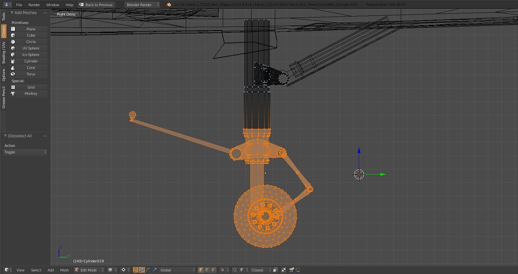
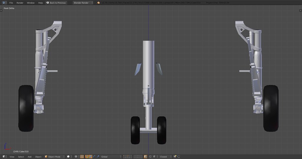
MLG:
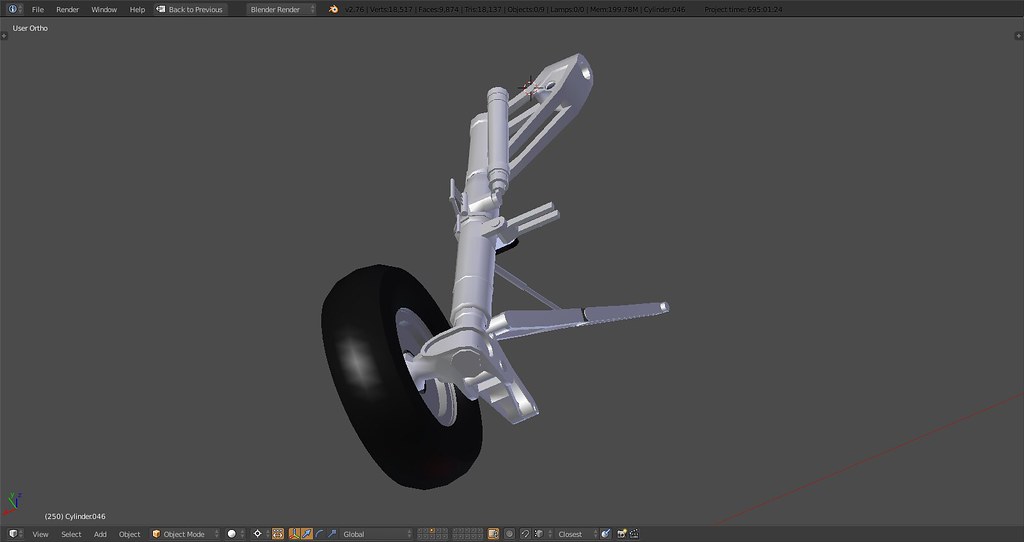
Some parts aren’t connected yet and the tires need some downtrimming so there are some tris to shed…prolly land at around 6000k for the main gear.
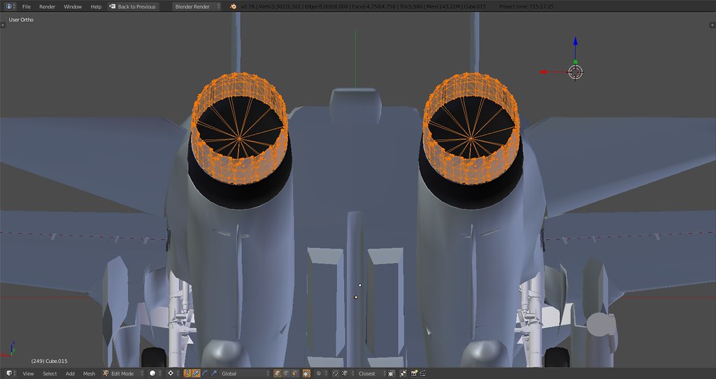
Nozzles now with only two inner parts:
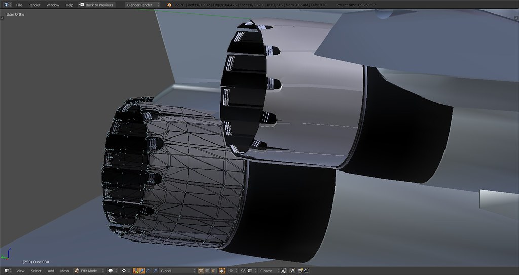

The ‘rings’ now sit on top of the second inside part of the engine outlet instead of one full ring all around.
-
Far above of what we dreamed…
-
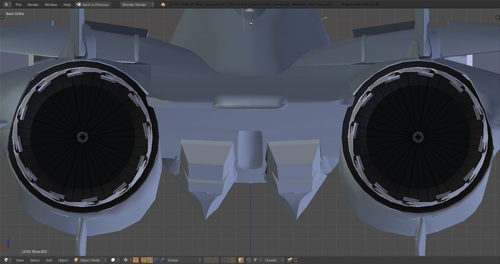
The F-110 nozzles are not mirror images but if there is a Falcon game engine restriction I understand. Right now it looks like the nozzles are mirrored off each other, they should be the same.
-
The F-110 nozzles are not mirror images but if there is a Falcon game engine restriction I understand. Right now it looks like the nozzles are mirrored off each other, they should be the same.
Not sure I catch your meaning. The nozzles are all the same (12x left and 12x right), duplicated off of the first one. There is no mirroring or other modification involved. The only asymmetry about the nozzles is the indentation on the top side as on the real thing. Most GE-F110 nozzles are modeled asymmetrically either due to insufficient research, errors or modeling compromises.
Maybe I’ll have to change them later on when it comes to animation but for now they’ll stay in their ‘original’ shape.
In case you’re referring to the mirror across the y axis you’re right they’re mirrored atm. Can’t apply a mirror and fix this (and others) until all details are finalized.
-
It’s nice isn’t it?
Yeah, at 2000+ tris I probably moved that part to the nice but another time layer :). Instead worked on mesh optimization and reduced the number of tris per wheel to under 1000:
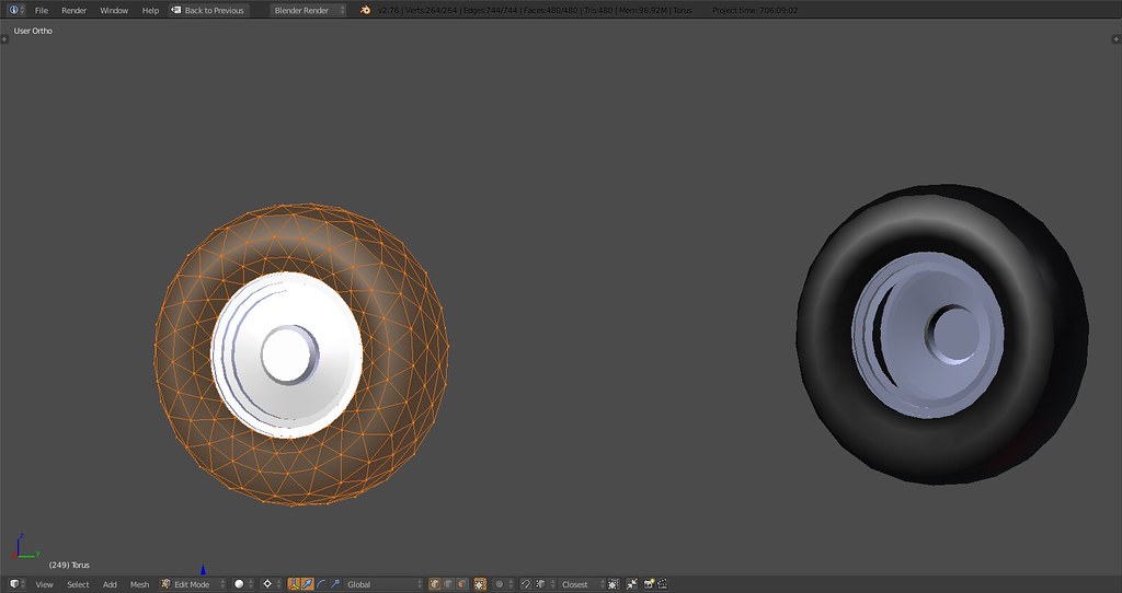

Before: 12.000 After: <3.000 - I like.
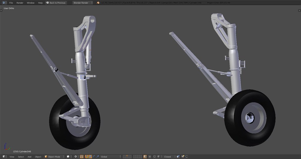
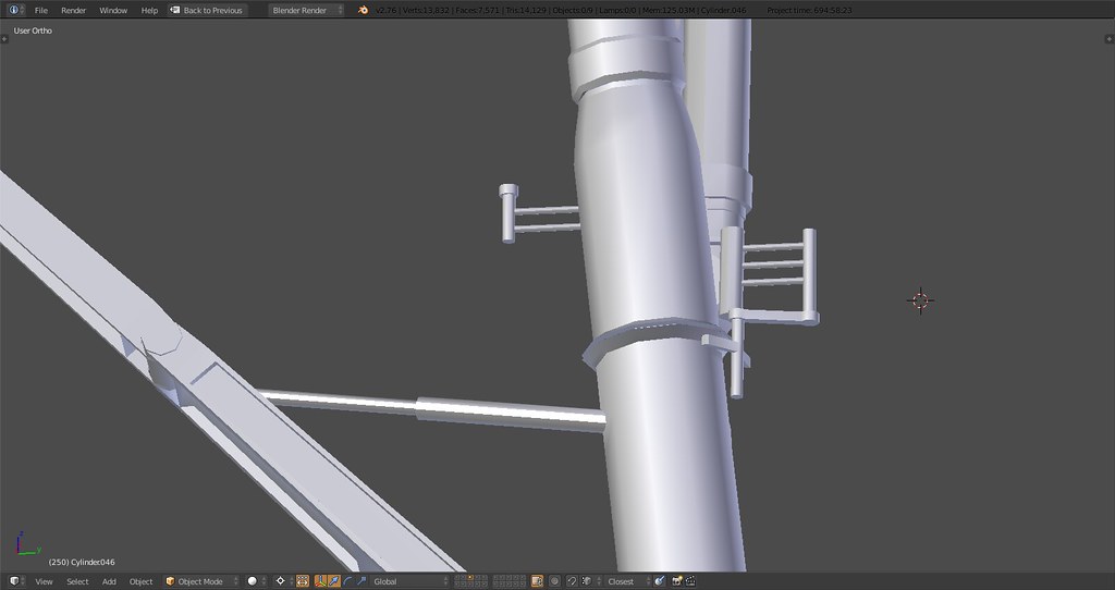
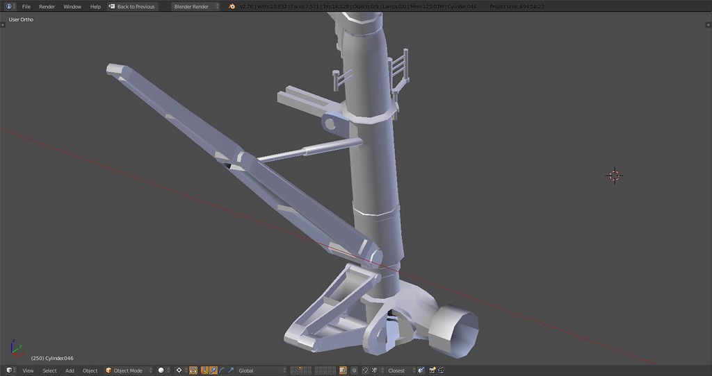
Then proceeded to the nose gear and made some progress. Parts have to be connected still but overall it’s getting close to the real thing. The whole geometry of the strut was wrong though which I only found out after I attached the nose gear strut actuator - corrected now.
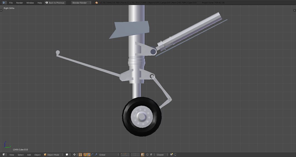
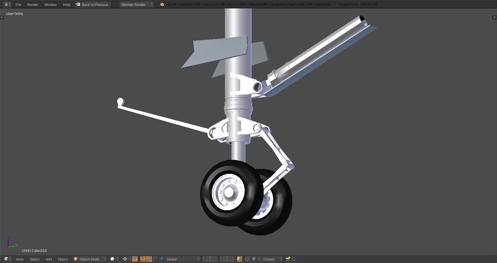
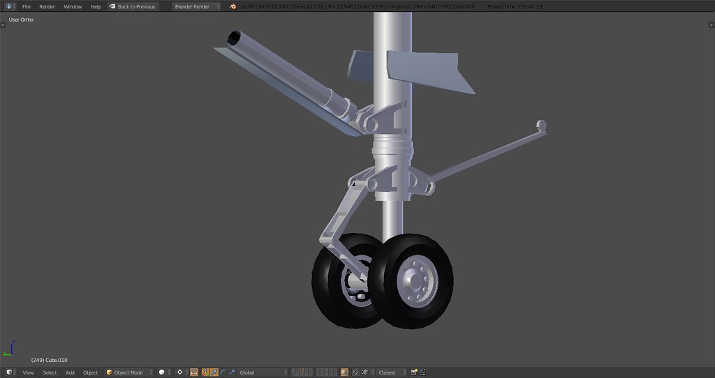
That nose gear is a beautiful assembly once it comes together. Looking forward to ‘welding it’ into one piece including landing light, the box and other details.
FYI you see the gear in the compression stage that a fully fueled, semi loaded Tomcat would have on deck. Main landing gear is almost fully compressed and front has enough room to kneel otherwise also compressed. Before it’s rigged it’s a pain to move all the parts…
-
Stunning. Do the nose gear indexer lights work in BMS? That would be fun to see from the flight deck.
I really can’t wait to see this thing in action…I suspect that some of the virtual VFA squadrons out there will become virtual VF squadrons in a hurry.
")
-
The F-110 nozzles are not mirror images but if there is a Falcon game engine restriction I understand. Right now it looks like the nozzles are mirrored off each other, they should be the same.
Stingray, I think what Turkeydriver ment is that your engines (on the images at least) have different petal “spin” - left engine spins anti-clokwise, and right spins clockwise. I think the petals should be arranged in the same direction… (view directly from behind)
-
Stingray, I think what Turkeydriver ment is that your engines (on the images at least) have different petal “spin” - left engine spins anti-clokwise, and right spins clockwise. I think the petals should be arranged in the same direction… (view directly from behind)
See last part of my post, what you’re describing is a mirror across the y axis of the plane. Meaning the left engine outlet and nozzle is mirrored horizontally across the axis thereby resulting in a ‘clockwise’ spin.
Currently the nozzles are part of the main fuselage object which means the mirror is applied to it as well. As long as the vertices on any part of the main body aren’t in their final position the mirror cannot be applied to make it one part because then any modification of any vertices will not be mirrored and potentially result in asymmetry.
To make it clear I know about the issue, it will be sorted out once the main body mirror is applied and then the outlets and nozzles will be separate parts and left will be duplicated and moved to the right. This issue applies to many parts of the model which is simply a result of modeling.
-
Stunning. Do the nose gear indexer lights work in BMS? That would be fun to see from the flight deck.
I really can’t wait to see this thing in action…I suspect that some of the virtual VFA squadrons out there will become virtual VF squadrons in a hurry.
Thanks :). I’ll model the lights and give it proper textures and functionality. Whether it works I can’t tell ya atm. Once I move it to Max and deal with prepping it for BMS I’ll deal with that stuff. That being said as far as I recall the whole (IFL)OLS and glidepath logic isn’t in the code.
As for the squadrons if LANTIRN FLIR and TCS are working in the D pit and the FM is tweaked accordingly I don’t see why anyone would follow the mandate and not his own choice:
Bugs by mandate - Tomcats by choice.
However, there’s so much false and outright misleading info out there about the big cat and tons of propaganda that’s been regurgitated beyond belief here and elsewhere I wouldn’t be surprised if the general reaction would be: nice to look at but pretty useless because ‘enter false reason of choice courtesy of Boeing lobby here’
")
Nobody cares, Baby.
-
See last part of my post, what you’re describing is a mirror across the y axis of the plane. Meaning the left engine outlet and nozzle is mirrored horizontally across the axis thereby resulting in a ‘clockwise’ spin.
Currently the nozzles are part of the main fuselage object which means the mirror is applied to it as well. As long as the vertices on any part of the main body aren’t in their final position the mirror cannot be applied to make it one part because then any modification of any vertices will not be mirrored and potentially result in asymmetry.
To make it clear I know about the issue, it will be sorted out once the main body mirror is applied and then the outlets and nozzles will be separate parts and left will be duplicated and moved to the right. This issue applies to many parts of the model which is simply a result of modeling.
Thanks! I missed that part, thanks for explanation
-
Great work with the landing gears mate, Bravo!!!
Keep on it.
Nikos. -
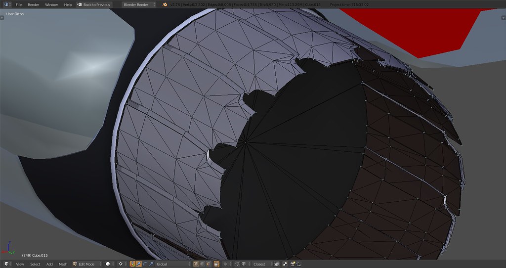
nth modification of the nozzles and inner plates. I’ll leave it for now but it is now not mirrored anymore
6000 tris with little reduction potential as 24 plates are needed one way or the other.

Took me a while to figure this out but one of the plates has to be rotated in order to achieve this look. In reality the dark spots are footprints the nozzles leave on eachother so that plate can be dropped and I’ll save around 800 tris. The look will be achieved by textures on the nozzles. Anyway impressive that this look is achievable with some materials and a ‘plate’ :D.

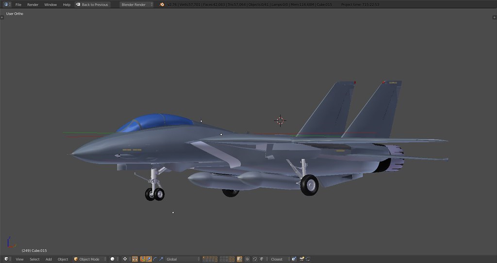
When the gear doors, nose gear details and wing roots are sorted out it’s time for some renders!
-
She’s a real beaty! Thank you!
-
Really solid and lovely work.
One issue I noticed about the petals. IRL they are actually symmetrical along their long axis. The asymmetrical “footprint” comes from the wear of the adjacent petal on the surface.
-
Really solid and lovely work.
One issue I noticed about the petals. IRL they are actually symmetrical along their long axis. The asymmetrical “footprint” comes from the wear of the adjacent petal on the surface.
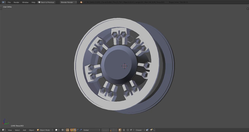
Thanks Pumpy, glad you like it. As for the petals, these are symmetrical which I tried to explain in my post above “In reality the dark spots are footprints the ‘petals’ leave on eachother so that ‘helper’ plate can be dropped and I’ll save around 800 tris. The look will be achieved by textures on the nozzles.”
I’m simply emulating the real look with my helper plate in the absence of textures. The petals are modeled based on the real thing, symmetric and with the small indentation on top:
-
Amazing detail and work! Can’t believe this is gonna be a reality!
-
Thanks Pumpy, glad you like it. As for the petals, these are symmetrical which I tried to explain in my post above “In reality the dark spots are footprints the ‘petals’ leave on eachother so that ‘helper’ plate can be dropped and I’ll save around 800 tris. The look will be achieved by textures on the nozzles.”
I’m simply emulating the real look with my helper plate in the absence of textures. The petals are modeled based on the real thing, symmetric and with the small indentation on top:
https://c2.staticflickr.com/9/8684/28126890833_45315daa29_b.jpg
Looks good now. Sorry, I was going by the meshes in the earlier pics.[emoji106]
Sent from my HTC6545LVW using Tapatalk
-
-
Do you have by any chance any pics with engine nozzles closed?
Very nice Tomcat!