Instrument landing system localizer off?
-
Incidentally you should still be cross checking against the TACAN which is your primary navigation aid. Source: AFTTP3-1 3.17 Navigation.
-
You made a slight typo: it is AFTTP3-3 3.17
-
I’m afraid you misunderstood the meaning of the paragraph.
It means even though F-16s can navigate RNAV, TACAN is still the widespread method of
navigation employed. This is the meaning of “primary” in the context of the paragraph.
While navigating by TACAN (in the sense of traditional/conventional radio navigation) you are permitted
to augment it with INS but are not permitted to substitute it with INS (i.e. refer only to INS data).
This is similar ,lets say to VFR flight with instruments (NDB, VOR, GPS etc.). Flying VFR doesn’t exclude
the use of instruments as aid but you are still obliged to refer to visual cues/references in the outside world and verify
your route/position by them. In this sense TACAN is the primary instrument (as the eyes are the primary “instrument” in the case of VFR).
-
-
Now … go practice :
(keep your attention on instruments please)I’m trying hard to do this…

Nikos. -
Trick, how to make digital 3D “pseudo ILS” from MarkPoint and 2 Offsets.
EMF: LARISA AB, RWY 08L
1. AA mode - make “OFLY” MarkPoint 26.
2. Go to NAV mode.
3. At DEST page add OA1 and OA2 to MarkPoint 26:
OA1 - RNG 6000 ft, BRG 259, ELEV 300 ft. With 300ft elev will be three degrees glide path to MarkPoint 26. 6000 ft approx 1 nm.
OA2 - RNG 11000 ft, BRG 79, ELEV 0 ft. (11000 ft - RWY length)4. Flight direction: OA1 - MarkPoint 26 - OA2
Heading: 79 degrees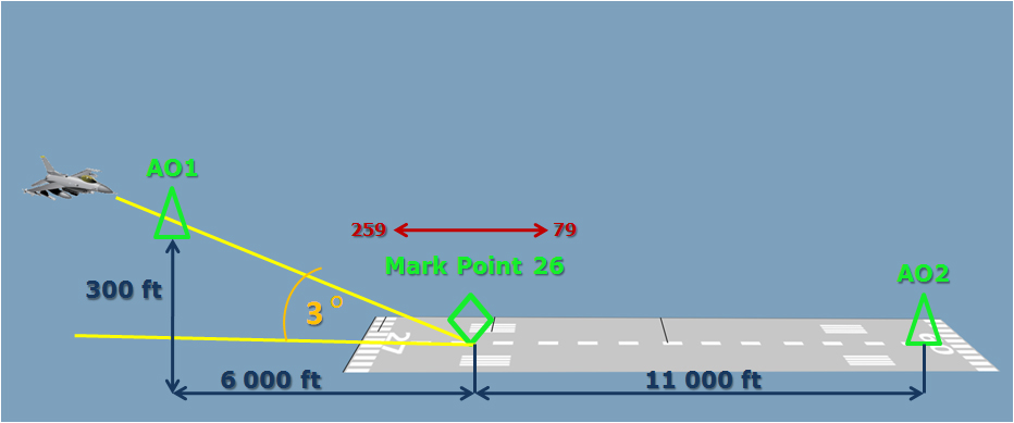
I made OA1 and OA2 points in order not to look at the HSI. I want to reduce pilot workload during landing. Instead of observing two 2D images, ILS and HSI, pilot looks only at the HUD with 3D image of the situation. Human brain with a stereoscopic vision is ten times faster processing 3D image than 2D. Our vision and brain created for hunting and always makes 3D situation image from multiple 2D images.
BTW, another advantage of the Mark Point - you can see on the HUD an accurate distance to the Threshold/Touchdown Zone.
-
… would be nice to see the same using real IMC conditions (ILS minimums visibility) and with the right approach AoA …
ASUSTeK ROG MAXIMUS X HERO / Intel Core i5-8600K (4.6 GHz) / NVIDIA GeForce RTX 3080 Ti FE 12GB / 32GB DDR4 Ballistix Elite 3200 MHz / Samsung SSD 970 EVO Plus 2TB / Be Quiet! Straight Power 11 1000W Platinum / Windows 10 Home 64-bit / HOTAS Cougar FSSB R1 (Warthog grip) / SIMPED / MFD Cougar / ViperGear ICP / SimShaker JetPad / Track IR 5 / Curved LED 27'' Monitor 1080p Samsung C27F396 / HP Reverb G2 VR Headset.
-
This post is deleted! -
… would be nice to see the same using real IMC conditions (ILS minimums visibility) and with the right approach AoA …
I made some AoA “shifts” to make “marks” visible ))) I think, this method with MarkPoint similar to the RNAV (GPS) Approaches.
P.S. BTW, how to make ILS minimums visibility ?
-
Slightly OT… is the BMS? I ask cos the HSD has labels on (JEW and TOL) I don’t think I’ve ever seen before… 4.33 beta?
-
ASUSTeK ROG MAXIMUS X HERO / Intel Core i5-8600K (4.6 GHz) / NVIDIA GeForce RTX 3080 Ti FE 12GB / 32GB DDR4 Ballistix Elite 3200 MHz / Samsung SSD 970 EVO Plus 2TB / Be Quiet! Straight Power 11 1000W Platinum / Windows 10 Home 64-bit / HOTAS Cougar FSSB R1 (Warthog grip) / SIMPED / MFD Cougar / ViperGear ICP / SimShaker JetPad / Track IR 5 / Curved LED 27'' Monitor 1080p Samsung C27F396 / HP Reverb G2 VR Headset.
-
HSD has labels on (JEW and TOL) I don’t think I’ve ever seen before… 4.33 beta?
Use WDP (PPT tab)
-
-
Slightly OT… is the BMS? I ask cos the HSD has labels on (JEW and TOL) I don’t think I’ve ever seen before… 4.33 beta?
With WDP you can make custom name/size PPTs.
-
I never knew that.
-
-
Trick, how to make digital “pseudo ILS” from MarkPoint and 2 Offsets.
EMF: LARISA AB, RWY 08L
1. AA mode - make “OFLY” MarkPoint 26.
2. Go to NAV mode.
3. At DEST page add OA1 and OA2 to MarkPoint 26:
OA1 - RNG 6000 ft, BRG 259, ELEV 300 ft. With 300ft elev will be three degrees glide path to MarkPoint 26. 6000 ft approx 1 nm.
OA2 - RNG 11000 ft, BRG 79, ELEV 0 ft. (11000 ft - RWY length)4. Flight direction: OA1 - MarkPoint 26 - OA2
Heading: 79 degreesHi there.
Well, since you have the GPS coordinates of the desired threshold, then you don’t need the OA1 and OA2 points.
Just place your FPM over the middle of STPT 26 (Markpoint of RWY threshold), keep the 2.5 deg. pitch ladder dive over the middle of STPT 26 and the top of AOA bracket side to the FPM (for an 11 deg. AOA approach).
Then you will have a perfect 2.5 deg. slope approaching ;).
Nikos. -
Hi there.
Well, since you have the GPS coordinates of the desired threshold, then you don’t need the OA1 and OA2 points.
Just place your FPM over the middle of STPT 26 (Markpoint of RWY threshold), keep the 2.5 deg. pitch ladder dive over the middle of STPT 26 and the top of AOA bracket side to the FPM (for an 11 deg. AOA approach).
Then you will have a perfect 2.5 deg. slope approaching ;).
Nikos.Hi! I need OA1 and OA2 points as a visual reference to keep the the correct flight path (79 degrees heading).
I was able to make successful landing with Minimum Visibility Landing (Fog 0 - 250) and 3 fuel tanks.
Not the best AoA for the heavy aircraft, but I landed. Need more practice )))12:55 - Approach
-
Hi! I need OA1 and OA2 points as a visual reference to keep the the correct flight path (79 degrees heading).
I was able to make successful landing with Minimum Visibility Landing (Fog 0 - 250) and 3 fuel tanks.
Not the best AoA for the heavy aircraft, but I landed. Need more practice )))12:55 - Approach
Nop, you don’t need them.
Just input at your HSI for course the exact heading of the runway and keep it centered ;).
Nikos. -
Nop, you don’t need them.
Just input at your HSI for course the exact heading of the runway and keep it centered ;).
Nikos.You are absolutely right! I made OA1 and OA2 points in order not to look at the HSI. I want to reduce pilot workload during landing. Instead of observing two 2D images, ILS and HSI, pilot looks only at the HUD with 3D image of the situation. Human brain with a stereoscopic vision is ten times faster processing 3D image than 2D. Our vision and brain created for hunting and always makes 3D situation image from multiple 2D images.
BTW, another advantage of the Mark Point - you can see on the HUD an accurate distance to the Threshold/Touchdown Zone.
")