WIP: F-14 B/D
-
Rudder hydraulic actuator housing…asymmetric so on the right side of both vertical stabs.


In retrospect I’d say these Grumman designers are certifiable, this part is actually worse than the wings :D. Finally got a rough form together.
-
Keep working it…

Nikos. -
Details, Baby!
-
stingray_SIX_TWO_ i can se you are working on Blender. (Nice and light program), my question is after you do anywork in 3ds? or you export in 3ds from blender and import wit LE? I think to start to work in Blender cause 3ds is a hell of a heavy program.
-
stingray_SIX_TWO_ i can se you are working on Blender. (Nice and light program), my question is after you do anywork in 3ds? or you export in 3ds from blender and import wit LE? I think to start to work in Blender cause 3ds is a hell of a heavy program.
Yeah I’m using Blender for all hard surface modelling pre- texture specifics, DOFs and some other details. You are correct, I’ll export to a file format 3ds can open and then use that and WaveyDave’s toolkit for the rest. Final import into BMS via LE with the three or four LODs. I hear you man, 3ds is not nearly as accessible as Blender but I guess it’s just a question of ‘time and tutorials’. I’m just postponing my 3ds learning curve as long as possible :D.
AFAIK from comments here and reading the guides and best practice material there is no problem with using Blender for hard surface modelling as long as you realize that eventually you’ll have to get a grip on 3ds anyway…
About it being heavy - it is the only program that actually takes noticeable time to boot up on my Lenovo, everything else (EVERYTHING) takes like 3 seconds or less.
-


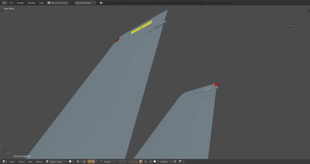

These stabs are a pain just like the actuator housing :D. Anyways the one detail still missing is the bulge around the pos light on the left stab. When that is done I’ll tilt them into their final position which is about 7 deg to the outside and then connect the base.
Helpful image of the day:

")
Vertical stabilization, Baby.
PS: The AC and Pos lights are modelled but separate objects, not sure if this can be used in the model or just textured…
-
PS: The AC and Pos lights are modelled but separate objects, not sure if this can be used in the model or just textured…
Yes they can be used.
Formation lights are on their own switch and can be dimmable.
-

Sometimes there’s no easy fix…
-
Nothing like a cut through to check your proportions…had a lot of bumpy lines on the bottom side. Smoothed them out and adjusted the curvature of the front fuselage on the lower side. Only got around to it cuz the weapon rail just didn’t seem to fit even though I modelled it almost to a tee of what the real thing looked like. Fortunately I did that now, woulda been a pain to adjust later on.


As almost every other part of this jet the rails are asymmetric:

Rails still need some refinement but overall shape and placement should be final:


-
You might have noticed the canopy

Bubble ahead…

The extrusion of the canopy and windshield frames will be reduced somewhat later on. Glass transparency only works once textures are assigned for the alpha as far as I know so for now it’s all sky blue.
-
Feel free to also check out other updates:
https://www.benchmarksims.org/forum/showthread.php?25067-WIP-F-14-B-D&p=365102&viewfull=1#post365102
https://www.benchmarksims.org/forum/showthread.php?25067-WIP-F-14-B-D&p=365104&viewfull=1#post365104
Further adjustments:
- rebuilt shape of aft side fuselage
- slimmed down the size of side fuselage around area where horizontal stab is attached
- stab can now rotate freely and has sharpened line extending to the main landing gear box
- cleaned up topside where vertical stab base sits
- rotated stabs into tilted position
- added AC lights
- moved main wing into final position (note the wingtip now sits between the lower end of the rudder and the engine nozzle)
- adjusted drop tank connector and position
- adjusted bottom side of beaver tail
What’s next? I’ll now have to weld together all parts, then finish the wings and build the outer weapon pylons. Then onto the gear…
Some impressions:


Time to assemble me, Baby.

-
Top work there, keep it up!
-
I’d say she’s coming along “smoothly”. The hype is real!
")
-
Awesome work Stingray!
-
Some impressions:
Time to assemble me, Baby.
Well one remark here my dear friend:
The ventral fins are the same and have the same shape both of them. Means they are not mirrored.
Check the below photos:

http://www.anft.net/f-14/f14-detail-fin-03.htm
Can you please correct it? Thanks a lot and keep your AWESOME work buddy

Nikos. -
Well one remark here my dear friend:
The ventral fins are the same and have the same shape both of them. Means they are not mirrored.
Can you please correct it? Thanks a lot and keep your AWESOME work buddy
Nikos.Eagle eye :). You’re right, the engine oil cooling duct is on the inside of the starboard fin.
The reason is that the fin is currently grouped with the engine pods and these are mirrored atm. It’s more convenient to adjust stuff like that once the mirror is applied in the end when all vertices are in their ‘final’ position.
PS: M.A.T.S. for the win!
I actually contacted Torsten a couple of years ago to use one of his pics - nice guy! -
Sometimes I feel you just need some motivation and inspiration when spending 100s of hours on modelling this most elegant of Naval jets to get every line right. So I figure I might as well share it
These are Alphas big in Japan in the 90s.
As one commenter put it…
Any Knight Baby.
-
Playing around with Blender’s render engine a bit…started the finalization of the wing pivot assembly and cover including the wrap around area on the glove…Meow, Baby.

-
This looks AWESOME!!! Thank you for your very hard effort on our Baby!
-
C’ on stingray, you are almost there!!!
THANKS A LOT.
Nikos.