WIP: F-14 B/D
-
Put some meat on the vertical stabs
Originally I made them way too thin.
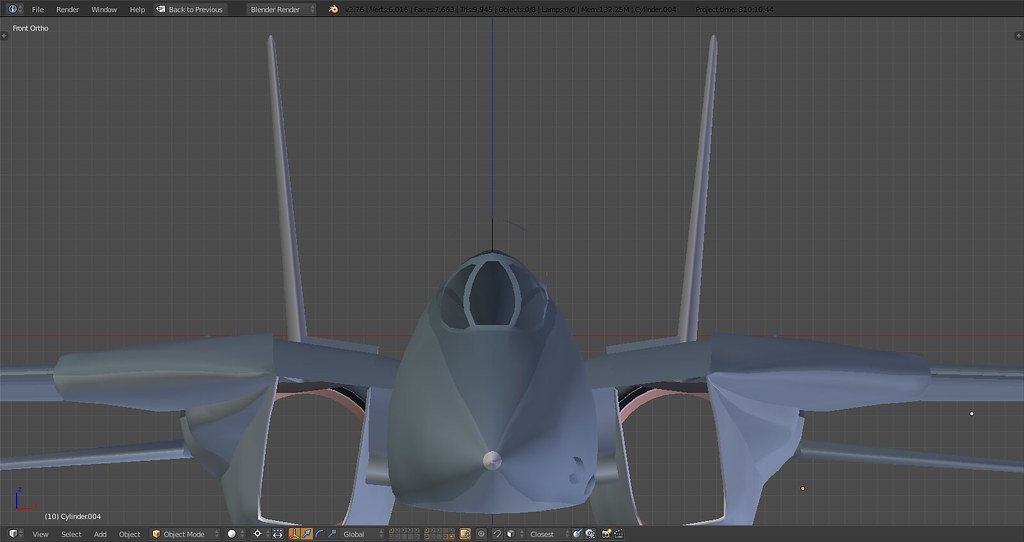
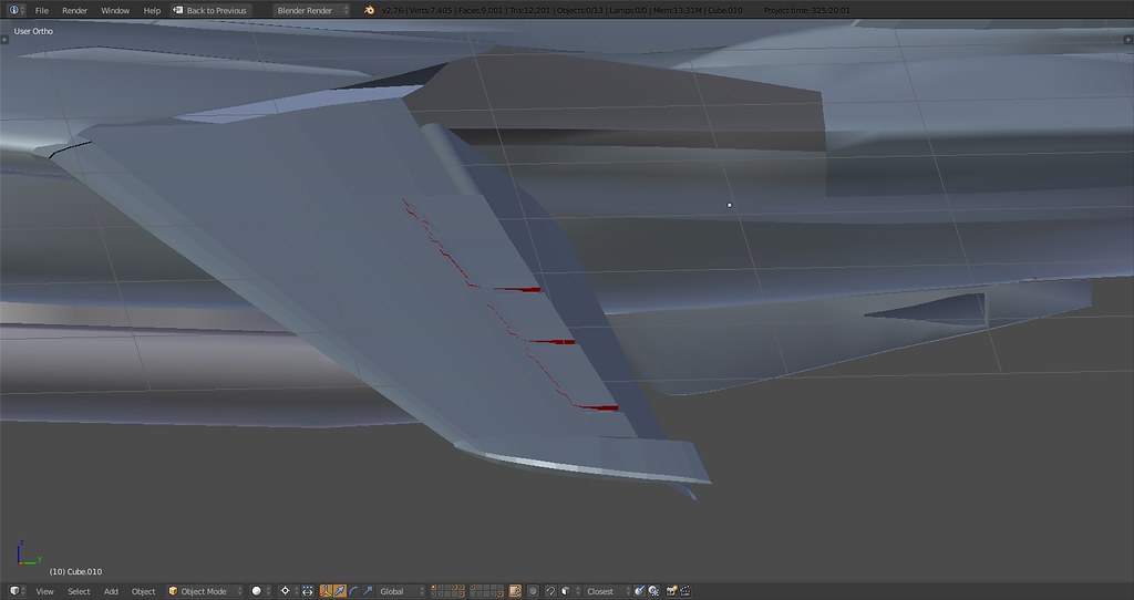
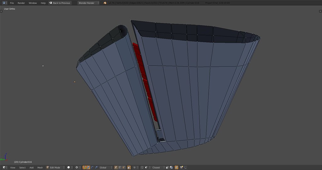
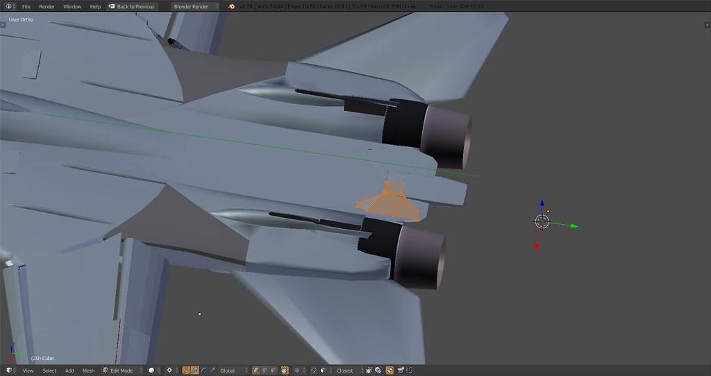
Separated the ventral fin into its original components. On the real thing the bow part of the fin is attached to the inner ‘weekly’ maintenance door and swings with the door to the inside while the aft part is attached to the rear part of the engine housing. Only thing on the aft part worth mentioning would be tow hooks that are rarely ever used in RL and won’t be modelled.
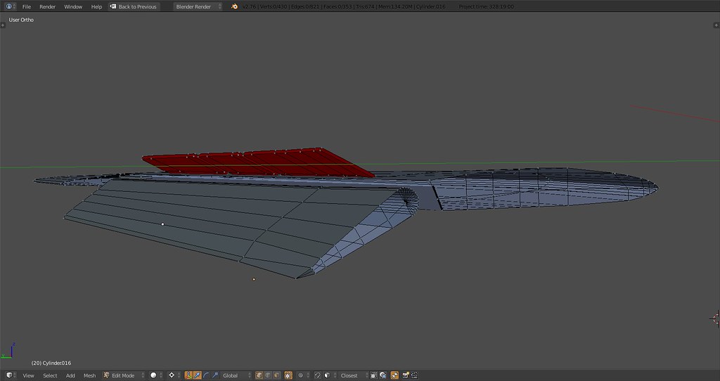
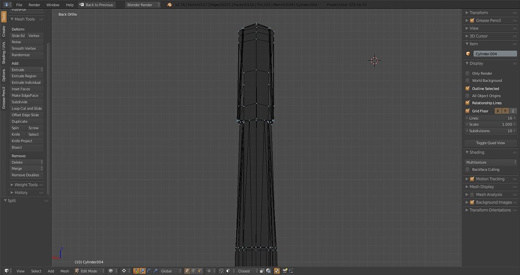
Stabilizer base in its final form. This part is symmetric and the same left and right. The hydraulic actuator housing attaches to the left of the base on both sides left and right.
-
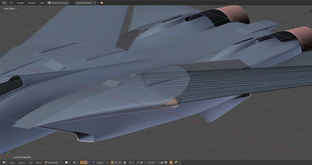
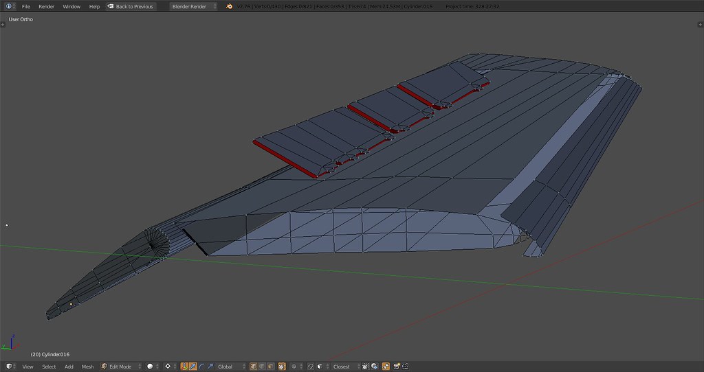
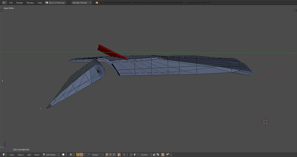
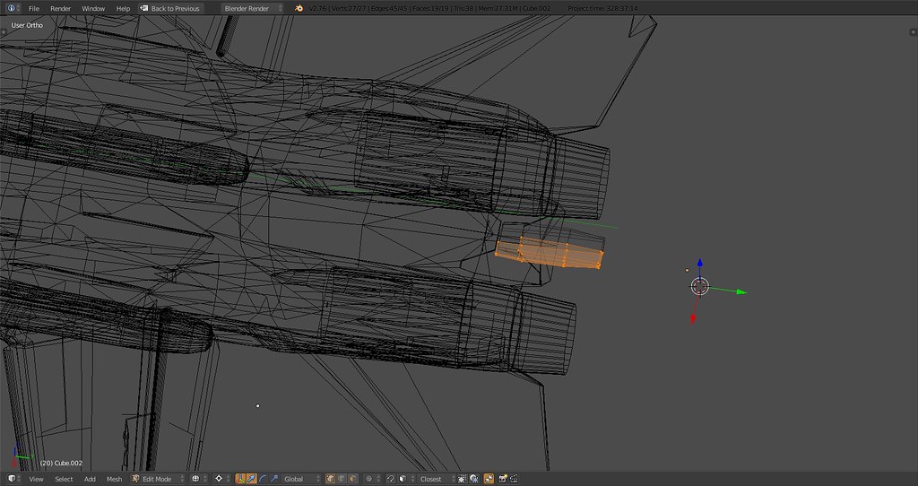
Starting to build the wing pivot assembly.
-
-
Its becoming really beautiful!
-
Separated the ventral fin into its original components. On the real thing the bow part of the fin is attached to the inner ‘weekly’ maintenance door and swings with the door to the inside while the aft part is attached to the rear part of the engine housing. Only thing on the aft part worth mentioning would be tow hooks that are rarely ever used in RL and won’t be modelled.
Hi stingray,
Your model is progressing nicely. When it comes time to lose polys (if needed) you may consider using textures for things such as the NACA ducts and the plate that the ventral fins are attached to.
-
Hi stingray,
Your model is progressing nicely. When it comes time to lose polys (if needed) you may consider using textures for things such as the NACA ducts and the plate that the ventral fins are attached to.
I will probably absolutely have to lose some polys so thanks for the comment.
I just figure I model this stuff now and see where I land in the end. I guess the big hitters apart from the gear and afterburner will be the slat, flap and spoilers with actuators and hinges on the wings and of course weaponry. Based on your experience, if I can stay below 20K with all that stuff you think 10K for the gear (including doors etc), afterburner (including nozzles) and vapor will suffice?
-
Just be sure to keep your original super high-poly version around so you can get blender to generate normal maps. Does anyone know if BMS uses normal mapping yet?
-
-
Put some meat on the vertical stabs
https://farm2.staticflickr.com/1660/23974897353_a3dc479afc_b.jpg
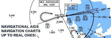
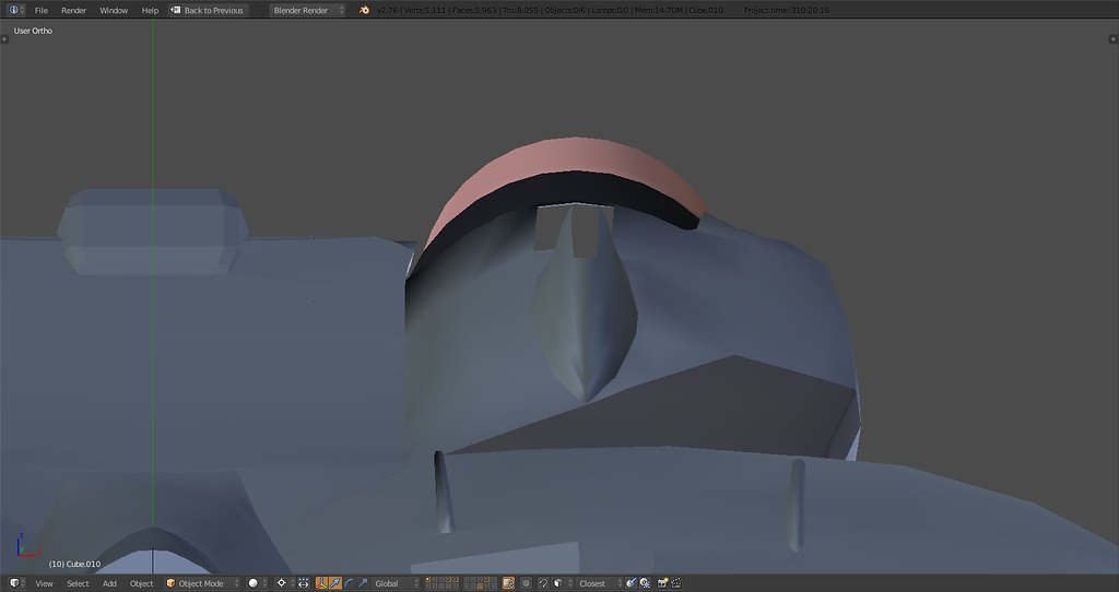
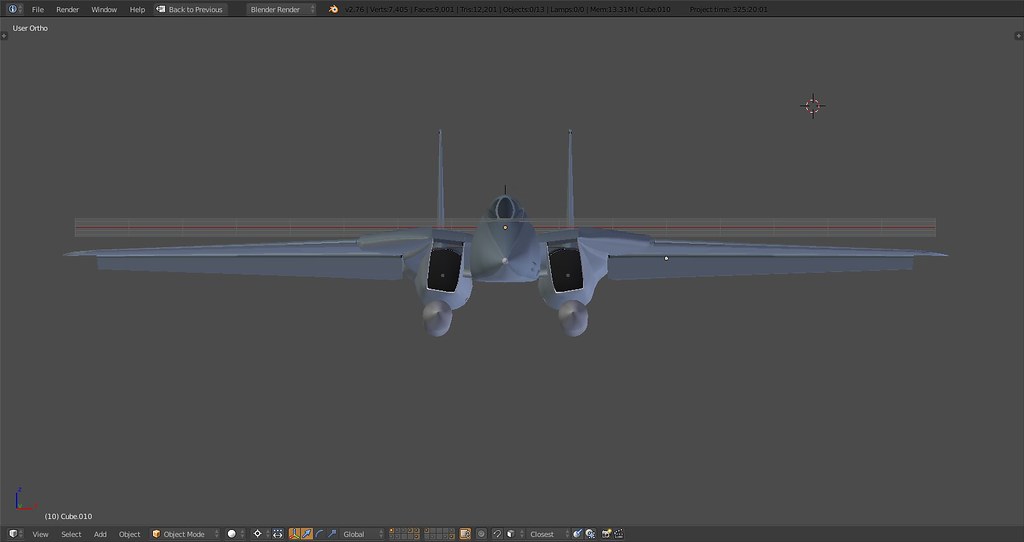
If you can modify the cockpit part when make a little bit bubble and height it. look like this photo:

good luck for it more
-
If you can modify the cockpit part when make a little bit bubble and height it. look like this photo:
http://cache3.asset-cache.net/gc/71888255-head-on-view-of-an-f-14-tomcat-gettyimages.jpg?v=1&c=IWSAsset&k=2&d=JewagDp3BOP93elYs4s58m2CpwWHv9x6nzNh8ywlv4smVAD%2Feg9c2VLCUwcVaQV0good luck for it more
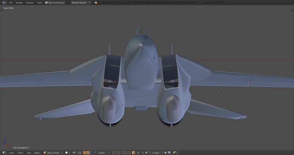
I haven’t modelled the canopy glass yet. If you go to the beginning of page 9 you’ll see the bubble shape in the center frame part ;).
That being said Tomcat has very little bubble shape as many of its peers from that era compared to later designs.
-
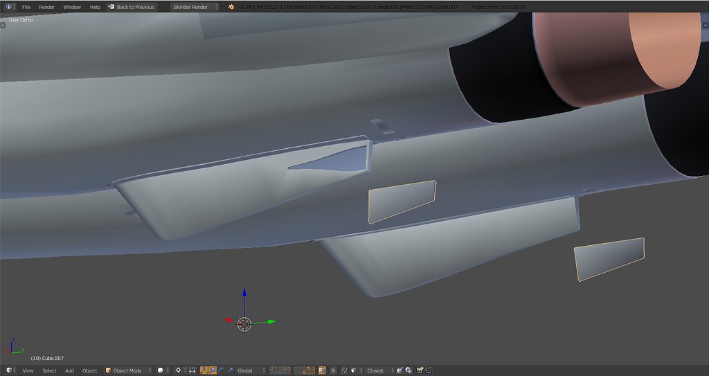
FLAPS!
As you can see and probably know already the Flaps as well as the forward ‘wing slat’ are the two moving parts that need to be animated in a non-linear fashion so if I’m not mistaken an armature using bones would be necessary as this cannot be done by manipulating the surface by simply using empties. Something that would probably need to be done in 3Ds. It’s possible to do it in Blender but I’m not sure what ‘gets lost’ during exporting. If someone knows more about it please share.
One thing that could be done to avoid the armature would be to model the flap hinges and simply rig them as to slide back and down along the y and z axis. Anyone have any idea what would be more appropriate? Same logic applies to the wing slats.
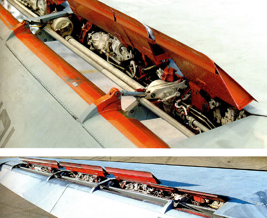
This is what it looks like. Flap is attached to connectors on the bottom side of the wing and moved via the hydraulic actuators on top which push back thereby rotating the flap along the pivot point of the lower hinge.
-
Movement looks as though it can be created via a Translation DOF coupled to a rotation DOF. Once you have the model in 3dsMax, WaveyDave’s exporter has some excellent tools for rigging with “bones.” You do have to have some knowledge about trigonometry, but it works. I’ll see if I can find the link to his video explaining the technique.
-
If you can modify the cockpit part when make a little bit bubble and height it. look like this photo:
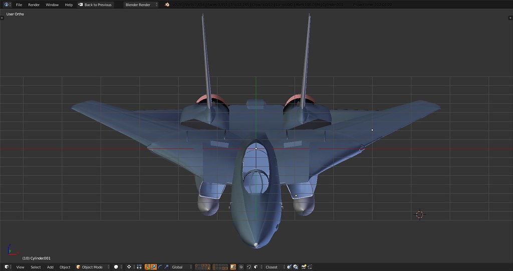
I think this is the perspective making the canopy look bigger. In the photo the camera is close to the plane and a little below, so the parts of the plane that are closer to the camera look very much larger than the parts at the back of the plane. Stingray’s images from blender are orthogonal, which means there is absolutely no perspective correction. Since we can never truly look at an object with 0% perspective correction (a caveat of living in a 3D universe), the best example I can come up with is this: they are more like looking at the plane from very far away with a zoom lens, where all the parts on the plane have no noticeable perspective scaling difference.
A trick you can do to visualize this difference is take an object like a small die-cast plane…um, yeah…I don’t have one either. Ok maybe a pencil. Close one eye and hold the eraser end (carefully) at a short distance from your open eye. The eraser end should look much larger than where the pencil starts to taper down to a point. Then, keeping one eye shut still to avoid stereoscopy’s additional depth cue, hold the pencil at arms length but at the same angle, in this part of the experiment both ends of the pencil (accept at the very end bit where it tapers to a point) should look much closer to the same size.
-
Movement looks as though it can be created via a Translation DOF coupled to a rotation DOF. Once you have the model in 3dsMax, WaveyDave’s exporter has some excellent tools for rigging with “bones.” You do have to have some knowledge about trigonometry, but it works. I’ll see if I can find the link to his video explaining the technique.
That’d be great if you could find that video.
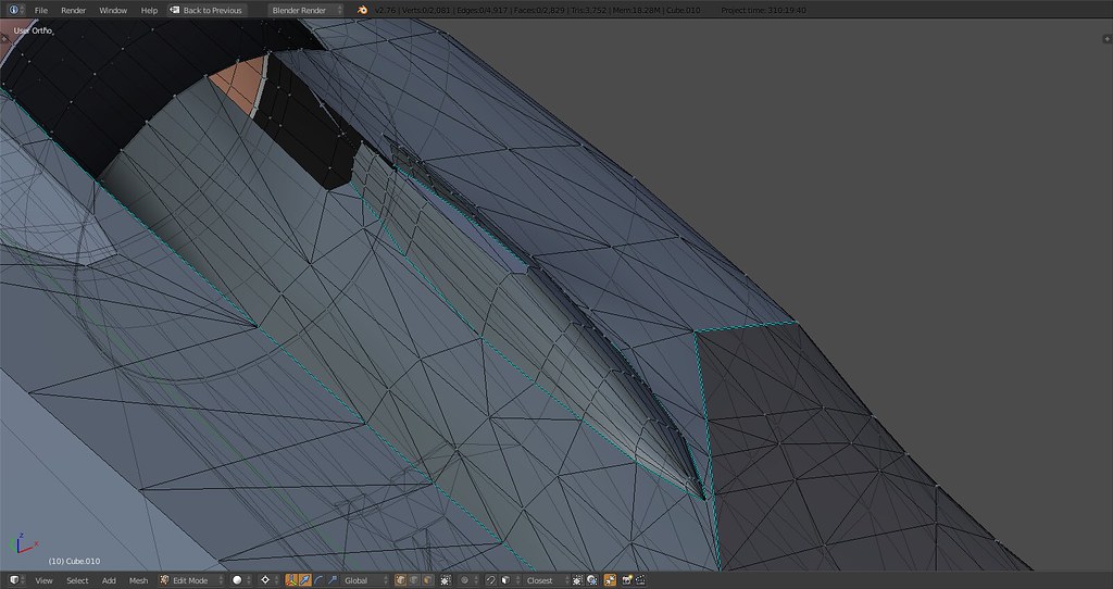
If you look at the profile view of the wing in reality the movement actually has 3 DOF, 1 heaving and 1 surging translation and 1 pitching rotation. I guess it’d be overkill to model it exactly so 2 DOF probably is most sensible. I definitely will model the top and bottom ‘flap doors’ also called eyebrow door and cove door. One tilts upwards (1 rotation DOF) when the flap is deployed closing off the gap between the center wing section and the tip of the flap. One is actually attached to the topside of the flap (1 rotation DOF). When flap is stowed it seals the gap between the wing and the flap curvature making it one straight surface. As the flap deploys the door tilts down and eventually merges down with the flap surface.
Lots of clumsy modeling but in terms of tris/polygons and rigging it shouldn’t be a problem.
Thanks for your help!
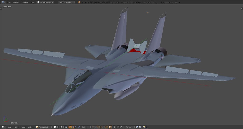
Some more impressions. Approx Flap down 20 deg, Spoilers up 35 deg, Cove Door fully closed, Slat up and Slat down 17 deg…
The wings make the cat, Baby.
-
Well done!!! Keep on the “baby” mate…
Nikos. -
That’d be great if you could find that video.
If you look at the profile view of the wing in reality the movement actually has 3 DOF, 1 heaving and 1 surging translation and 1 pitching rotation. I guess it’d be overkill to model it exactly so 2 DOF probably is most sensible. I definitely will model the top and bottom ‘flap doors’ also called eyebrow door and cove door. One tilts upwards (1 rotation DOF) when the flap is deployed closing off the gap between the center wing section and the tip of the flap. One is actually attached to the topside of the flap (1 rotation DOF). When flap is stowed it seals the gap between the wing and the flap curvature making it one straight surface. As the flap deploys the door tilts down and eventually merges down with the flap surface.
Lots of clumsy modeling but in terms of tris/polygons and rigging it shouldn’t be a problem.
Thanks for your help!
Some more impressions. Approx Flap down 20 deg, Spoilers up 35 deg, Cove Door fully closed, Slat up and Slat down 17 deg…
https://farm2.staticflickr.com/1698/24389166410_95b8a692e9_b.jpg
https://farm2.staticflickr.com/1550/24316995589_e5df75ec9e_b.jpg
https://farm2.staticflickr.com/1446/24316995669_acc99057fb_b.jpg
https://farm2.staticflickr.com/1681/24684672215_24b0b298f5_b.jpg
The wings make the cat, Baby.
we can change that values in dat file later
")
compliments!
System specs:
Win10 pro - MB: Asus Z390H - CPU: i7 9700 - RAM: HyperX 2x16GB 2400 DDR4 - GPU: Nvidia 3060ti - HD: Corsair MP600pro m.2 1TB - JOY: TM 1600 - TIR 5 - MONITOR: AOC CU34G2X
-
we can change that values in dat file later
compliments!
Thanks.
I just wrote down the values to indicate the position of the surfaces in the posted shots. Am aware of the .dat file.
-
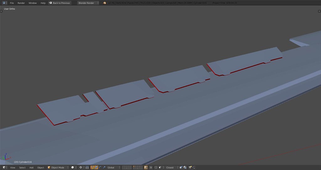
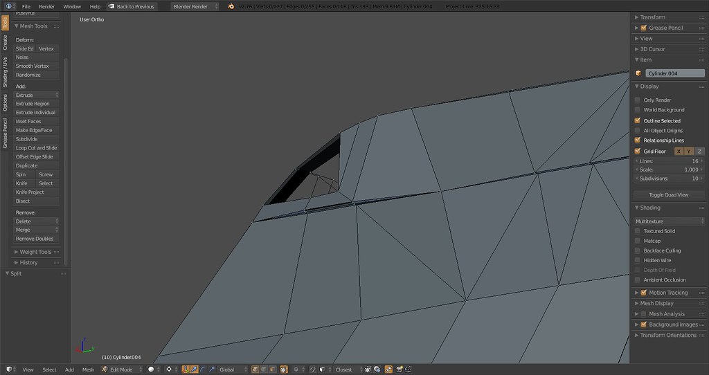
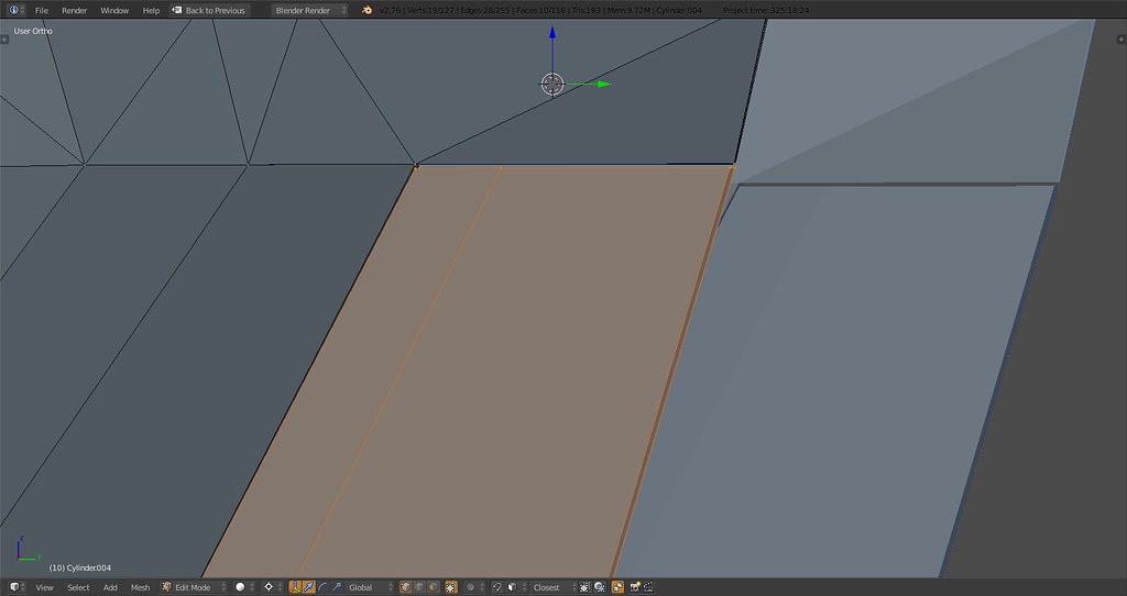
Narrowed down spoilers and inserted ‘gap’. The gap will eventually be positioned near the center of the inner spoiler where one of the flap hinges is located.’
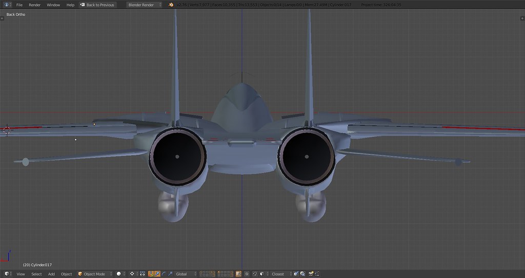
Noticed an error near the beaver tail. My fuselage only extended to the engine shroud and not as is correct to the engine nozzles. Now corrected.
Added canopy vertices, started on forward weapon rail. Drop tanks moved slightly outward and rotated as on the real thing. That said, the drop tanks will be re-modelled later as I didn’t use a mirror modifier when I first modelled them.
Following Pumpy’s hint I removed the ventral fin assembly. During that operation I noticed on ref images that these fins actually are positioned slightly inward below the center of the engine nozzles. Also note the slightly rotated drop tank and fin position inward. Also extended the engine to the point where the turbine outlet sits, detail will be add
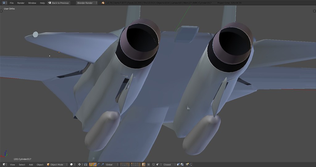
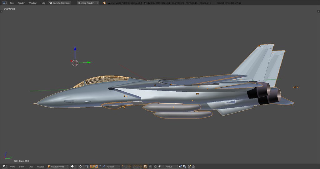
In case you were wondering the vertical stabs are straightened for now at 90deg to allow detailed editing…
13K tris at the moment. The wings will require at least another 1000 mainly due to the actuators and stuff. Anyway, the entire bird without gear and AB might actually be close to 15K which would be great given the level of detail which was the goal from the beginning.
-
Superb!
-
:bdance:
Freaking hard work. thanks mate.!!! looks awesome