JanHas Models & Skin Thread -Compatible with 4.36
-
Sorry then, I wrongly used the POAF acronym for Polish Air Force, instead of the correct POLAF.
Apologies accepted
 hehehe
Just messing with you Raptor
")
-
Not a good idea to mess with a Raptor… hahahhaha
-
More information i guess.
Mav?
The engine control system (ECS) comprises a primary (PRI) digital control and a secondary (SEC) hydromechanical control mode. PRI offers all the advantages of DEEC/IDEEC and runs the engine scheduling across the full range of throttle positions. SEC is a backup mode and will be discussed later on. Since the PW-229 is more powerful than the PW-220, IDEEC incorporates a ground idle thrust (GIT) setting to mimic the PW-220 performance when taxiing on the ground. IDEEC also incorporates a transient idle control logic that gives the pilot freedom to snap the throttles to idle whilst the engines maintain about 79% rpm. Thrust is reduced in accordance with requested throttle settings, but the engines maintain core rpm momentum for 20 seconds - after this they return to idle if no further throttle commands are given. This elongates engine life and improves subsequent throttle response times. The pilot has override authority on the operating mode of the ECS vie engine control switches, so the pilot can re-enter PRI mode and enter SEC mode if he desires so. This is achieved by the engine control switches: ON is for PRI mode, OFF is for SEC mode.
The DEEC schedules engine and afterburner fuel flows, compressor inlet variable vanes (CIVV), rear compressor variable vanes (RCVV), start bleed position, anti-ice and nozzle position. The DEEC controls engine performance by scheduling engine fuel flow to control airflow and nozzle position to control engine pressure ratio (EPR), this latter being a ratio between exhaust and inlet pressures. By controlling airflow and EPR, the engine performance remains consistent for a new or deteriorated engine until the FTIT limit is reached.
If a fault is detected by in the PRI mode software, then SEC mode is entered automatically. Note that SEC mode can be entered manually by placing the engine control switch to OFF position. SEC mode inhibits afterburner use and limits MIL power to 70-80% of its normal value. The CIVV are in a fully closed position, the nozzle is closed near to its minimum area (below 5%). In the meantime L or R ENG CONTR caution is displayed. RCVV, start bleeds and engine fuel flow are scheduled by the MFC. The engine remains in SEC mode until the fault is cleared or the engine control switch is put back to ON position.
Note that engine start can be accomplished with the engine control switches in either ON or OFF position, but after engine start they should be left in their position for at least 1 minute, otherwise DEEC will switch to SEC mode. If the engine is started with its engine control switch in OFF position then SEC mode will be entered immediately of course - this way ground starting time will be longer.
The F100-PW-220/229 incorporates a built-in engine monitoring system (EMS) which consists of DEEC/IDEEC software and the EDU (Engine Diagnostics Unit). This continuously monitors engine parameters and system states to detect engine operating failures. Engine operation failures (along with engine and aircraft data) are detected and logged in memory for further analysis by maintenance personnel. The EDU also maintains engine life-cycle information.
he exhaust nozzles (12) are axially symmetrical and they follow a convergent-divergent profile. They give a wide range both in area and in profile. The nozzles can be moved pneumatically by utilizing engine bleed air. The nozzles themselves are moved by titanium rods (11) driven by actuators (9). On the ground (when WOW is sensed) and the engine is in IDLE, the nozzles are 80% open with PW-220 engines and 90-100% open with PW-229 engines (provided that DEEC/IDEEC is on). As the throttles advance toward MIL, the nozzles are moving to their fully closed position.
During flight the nozzles are at their minimum area at all times, except at MIL power or on afterburner. At MIL nozzles are 5-10% open with PW-220 engines and 6-20% open with PW-229 engines. The nozzles reach their fully open state only in full afterburner to compensate for increasing afterburner fuel flow. -
The data for nozzle position in the fm file is a bit of mystery to me. How they all work together? I’m sure I can figure it out with a lot of trial and error. I’m not a big data editor and I prefer to spend my time on other models. If someone finds better values that can make it look/work better I’m sure I will add the new values to the fm’s.
-
I have released the LV3 F-16I and added it to the existing F-16I CFT package. Download via my website; janhas dot net

––
I have also finished the ITER model. The package has two sets of models and you have to choose which one you want to use. There is the high detail LOD1 (HD) and the other one is the lower detail LOD1 (LP). Use the texture of the version you install! If you use the wrong texture you will notice it. The model has been added to the “F-16 fuel tanks & pylons v3” package. Use the same install procedure as with the other LV3’s. That v3 package also has a fixed 370 gallon tank LOD1 model. There was a see through issue with the red refuel hole on top of the tank.
––
Next is the LV F-16D block 52. -

-
Sorry for silly question: it’s suppose to be a fuel tank folder within ALW7? Cause I’m not been able to found out “F-16 fuel tanks & pylons v3” anywhere.
-
Sorry for silly question: it’s suppose to be a fuel tank folder within ALW7? Cause I’m not been able to found out “F-16 fuel tanks & pylons v3” anywhere.
The pylons and tanks are on the LV3 F-16’s page (right of F-16CM-52).
-
Big like an home!!! I’m very sorry,
Many thanks -
Sweet what is next?
Intel Core i9-12900KF 3.2 GHz Processor; ASUS Strix Z690-F Motherboard; G.Skill Trident RGB 32GB (2x16) DDR5 5600 MHz Memory; EVGA GeForce 3090 RTX 24 GB Video Card; LG 34 inch 21:9 Curved UltraWide QHD IPS Monitor; 2 8 inch CubeSim MFD Monitors, SimGear ICP, FSSB R3L Ultra MkII Stick Base with Thrustmaster F-16 Grip, Thrustmaster Viper TQS Mission Pack Throttle Setup, Thrustmaster MFD Buttons, Track IR 5, HP Reverb G2 VR Headset; Windows 11 Pro 64 Bit
-
Sweet what is next?
I’m now deconstructing the F-16I and adding parts to make it into the F-16DM-52. It will have a single skin the 16th WS (WA) since that squadron has 4+ F-16D’s. The Swamp Fox unit has only 2 D’s (924 & 925).
-
This is very good news.:D
-
Hi Jan, is this particular version somewhere in the horizon?
")
-
It’s planned. Somewhere close after the HAF D52+ model.
-
The data for nozzle position in the fm file is a bit of mystery to me. How they all work together? I’m sure I can figure it out with a lot of trial and error. I’m not a big data editor and I prefer to spend my time on other models. If someone finds better values that can make it look/work better I’m sure I will add the new values to the fm’s.
Jan its ok mate i will send you a PM latter today with my modified .dat for you check. Did you see what i mean about the LG up/down sequence?
-
Hi Jan, is this particular version somewhere in the horizon?
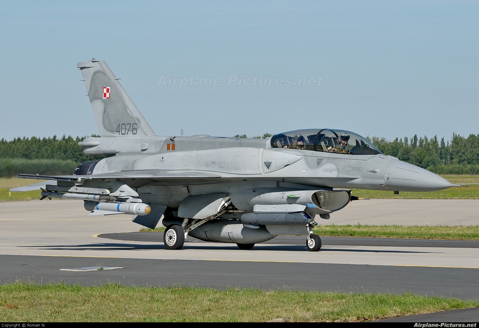
https://cdn.airplane-pictures.net/images/uploaded-images/2010/7/30/97189.jpgThe dude in the back looks like he’s just had his mind blown.
Harry (Formerly Amraam at Frugals etc.)

(I'm not currently active with ViperDrivers, but these guys are the best BMS school out there!)
-
The data for nozzle position in the fm file is a bit of mystery to me. How they all work together? I’m sure I can figure it out with a lot of trial and error. I’m not a big data editor and I prefer to spend my time on other models. If someone finds better values that can make it look/work better I’m sure I will add the new values to the fm’s.
I will make you very confortable then
–-------------------
Nozzle Max Chart
Determines the maximum NozzlePosition in AB depending on Mach and altitude
auxaerodata:
nozzleMil x , determines the maximum Nozzle Position value in MIL
LGIdle (0/1) : if set to 1 , Nozzle has different behavior LG down / up
nozzleIdleLGUp : position of nozzle in Idle LG up (not in 4.33)
nozzleIdleLGDown : position of nozzle in Idle LG down (not in 4.33)This controls the NozzlePosition value, this value is used both for Nozzle Gauge and Nozzle DOF
From that value , the DOF of nozzle is derived, and there is an aditionnal layer to adjust the DOF vs the NozzlePosition value
animExhNozIdle : not used
animExhNozAB : not used
animExhNozABMax : not usedanimExhNozMil (ther is a typo here, that should be animExhNozMin but will not be changed) : is the minimum DOF value when NOzzlePosition value is 0
animExhNozMax : is the maximum DOF value when NOzzlePosition value is 1animExhNozRate : si the speed rate of the DOF
-
The dude in the back looks like he’s just had his mind blown.
He’s saying: “I can’t believe how detailed this model is!” :woohoo:
-
I will make you very confortable then
–-------------------
Nozzle Max Chart
Determines the maximum NozzlePosition in AB depending on Mach and altitude
auxaerodata:
nozzleMil x , determines the maximum Nozzle Position value in MIL
LGIdle (0/1) : if set to 1 , Nozzle has different behavior LG down / up
nozzleIdleLGUp : position of nozzle in Idle LG up (not in 4.33)
nozzleIdleLGDown : position of nozzle in Idle LG down (not in 4.33)This controls the NozzlePosition value, this value is used both for Nozzle Gauge and Nozzle DOF
From that value , the DOF of nozzle is derived, and there is an aditionnal layer to adjust the DOF vs the NozzlePosition value
animExhNozIdle : not used
animExhNozAB : not used
animExhNozABMax : not usedanimExhNozMil (ther is a typo here, that should be animExhNozMin but will not be changed) : is the minimum DOF value when NOzzlePosition value is 0
animExhNozMax : is the maximum DOF value when NOzzlePosition value is 1animExhNozRate : si the speed rate of the DOF
Mav sorry for the bother but the line animExhNozIdle worked for me in the Jan dat file.
I corrected using the information you send the following lines:
nozzleMil 0.05 ( open to discussion for the PW-220 engine)
animExhNozIdle 32.0 ( it was set to 0)The changes in the line put the nozzle operating like you said always closed from idle to Mil with LG up. It opens very little close to Mil to mach the 5% opening.
The full line code is the following:
typeEngine 0
nEngines 1
engine1Location -18.7 0.00 -0.31
engine2Location 0.00 0.00 0.00
engine3Location 0.00 0.00 0.00
engine4Location 0.00 0.00 0.00
engineSmokes 0
normSpoolRate 3.0
abSpoolRate 10.5
nozzleMil 0.05
LGIdle 1
jfsStartUpTime 15
jfsSpoolUpRate 15.0
jfsSpoolUpLimit 0.25
lightupSpoolRate 20.0
flameoutSpoolRate 35.0
jfsRechargeTime 60
jfsMinRechargeRpm 0.12
jfsSpinTime 240
FTITStart 6.100
FTITIdle 5.100
FTITMax 7.600
FTITAB 7.623
mainGenRpm 0.63
stbyGenRpm 0.55
epuBurnTime 600
DeepStallEngineStall 1
engineDamageStopThreshold 15
engineDamageNoRestartThreshold 3
engineDamageHitThreshold 40
complexnozzle 1
animExhNozIdle 32.0
animExhNozMil 32.0
animExhNozMax -5.0
animExhNozAB 0
animExhNozABMax 0
animExhNozRate 50.0
PropEngineSwitchStates 0
animEngineRPMMult 10
HeatBlurShift -7
hasReverseThrust 0 #Added Falcas
ReverseThrustFactor 0.0 #Added Falcas
minReverseThrustSpeed 0 #Added Falcas
animReverseAngle 0 #Added Falcas
animReverseRate 0.0 #Added Falcas -
Mav sorry for the bother but the line animExhNozIdle worked for me in the Jan dat file.
I corrected using the information you send the following lines:
nozzleMil 0.05 ( open to discussion for the PW-220 engine)
animExhNozIdle 32.0 ( it was set to 0)placebo effect, animExhNozIdle is not used in the code , put whatever value in there , there will be no change.