WIP: F-14 B/D
-
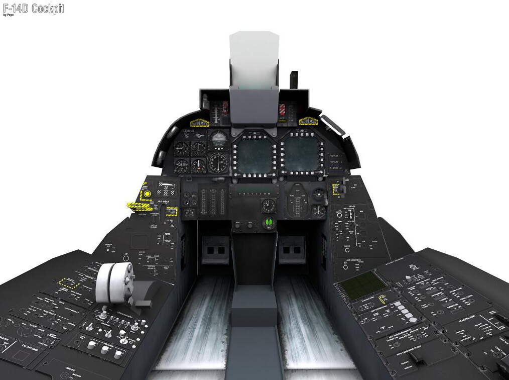
The seat-belts could do with a little more love, but…
WOW.
All kidding aside when you look at the actual seat it’s sorta tricky to decide what to model and what detail to leave to textures…in any case the belts will stay in 3D, I might even model them in 4D with contrast stitching and detailed fibers.
-
What about cockpit? Is there any plan who for it? Even without WIP cockpit of Mykinge flying with F-14 is not fun, or not even practical.
‘What about cockpit?’ That’s the question of all questions isn’t it? As was said in Hamlet “Conscience and grace, to the profoundest pit!”.
Anyway as you say without MyKinge’s WIP cockpit flying the F-14 is not fun nor practical - to that I say then we shall fly WITH it.
-
The Myking’s WIP cockpit was only available in Korea 80’s theater, and it was good to fly with it, but in 4.33.3 we haven’t this pit, it’s unfortunate…

-
What about pit from EBS and their KoreaHD mods?
-
What about pit from EBS and their KoreaHD mods?
NO GO. Copyright infringement was their downfall. Just an FYI, please don’t link to the site.
C9
-
Damn, so it looks like somebody must create again pit for this beast then, which is ofc waste of resources if somebody already did it. Same goes with stupid patent wars, why i would need to invent wheel if somebody already done it but he holds patent for it, for the sake of technological progess all patents should be free to use, then you can focus your resources for improving it to perfection … but this is for another debate and nothing is that simple as it sounds
")
-
Damn, so it looks like somebody must create again pit for this beast then, which is ofc waste of resources if somebody already did it. Same goes with stupid patent wars, why i would need to invent wheel if somebody already done it but he holds patent for it, for the sake of technological progess all patents should be free to use, then you can focus your resources for improving it to perfection … but this is for another debate and nothing is that simple as it sounds
Take it easy. The pit you’re refering to is not a D pit anyway. MyKinge has submitted his D pit entirely to someone at BMS and I’m sure we’ll find a way to finish and implement it. So just as it seemed highly unlikely that I would ever get to this point (remember a comment like ‘leave it to 3d modellers instead of wasting your time’) I’m just as confident that anything is possible and this pit will see the light of day just as this model will.
By the way I just noticed an inconsistency with my pilot side panel and the little extension on the vertical console - will correct asap :).
-
Stingray, you can always pull a rabbit out of your hat.
-
Does anyone by any chance know the max and min rotation limits on the horizontal stabilizers and rudders? I have all other limits for wing surfaces and doors but can’t find this anywhere.
-
Does anyone by any chance know the max and min rotation limits on the horizontal stabilizers and rudders? I have all other limits for wing surfaces and doors but can’t find this anywhere.
Rudder : +/- 30° maximum. Can be further limited depending on AOA and landing gear/ flaps on. With DFCS on, limited to 19°.
Horizontal stabilizers : EDITED : actually, +33° (pitch up) / -10° (pitch down).
Source : F-14 NATOPS (Page 2-100 and up). -
Rudder : +/- 30° maximum. Can be further limited depending on AOA and landing gear/ flaps on. With DFCS on, limited to 19°.
Horizontal stabilizers : EDITED : actually, +33° (pitch up) / -10° (pitch down).
Source : F-14 NATOPS (Page 2-100 and up).Sweet! Thanks, didn’t think to check the NATOPS now that you mentioned it.
-
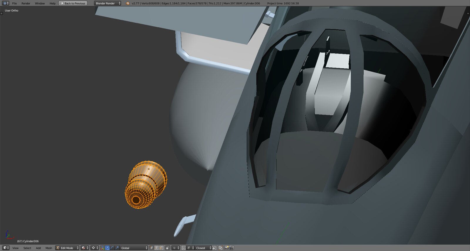
Now that the pit is done (pending the sticks and some minor adjustments) it’s on to the wings and surfaces and actually to the end of hard surface modelling in Blender. So now optimizing and ‘perfecting’ the mesh(es) and getting everything to work (also started on the refueling probe
is in focus as well as modeling the insides like the inside of the wing body and glovebag etc. -
If this can help you for the refueling probe, check this out
 :
: -
Duuude that is an awesome resource. Very useful for overall dimensions and animation. I’ve seen that before at some point but couldn’t find it when I was scouting for refs yesterday. Thanks a bunch!
Here’s what I started 2 days back
Luckily the refueling probe is one of the very few parts of the Tomcat that is fairly standard and simplistic in nature :).
-
Duuude that is an awesome resource. Very useful for overall dimensions and animation. I’ve seen that before at some point but couldn’t find it when I was scouting for refs yesterday. Thanks a bunch!
Here’s what I started 2 days back
https://c1.staticflickr.com/3/2202/32879365246_1898d3511e_h.jpg
https://c1.staticflickr.com/3/2300/32879364866_ba7901f984_h.jpg
Luckily the refueling probe is one of the very few parts of the Tomcat that is fairly standard and simplistic in nature :).
Hello!
Great work of yours! Nevertheless I feel your refuel drogue maybe has a bit too much triangles?
Do you think it’s worth spending so much tris in it?
Kind regards,
Radium
-
Hello!
Great work of yours! Nevertheless I feel your refuel drogue maybe has a bit too much triangles?
Do you think it’s worth spending so much tris in it?
Kind regards,
Radium
Thanks! Of course not but with easy to model things like that I like to create something nice in the beginning so I can enjoy its look throughout the modeling process while dealing with the latches, doors and general shape, dimensions and angle. Later on I trim things down to something a bit more reasonable.
Having a refueling probe with more polys than the entire cockpit including the seats would be interesting :D.
-
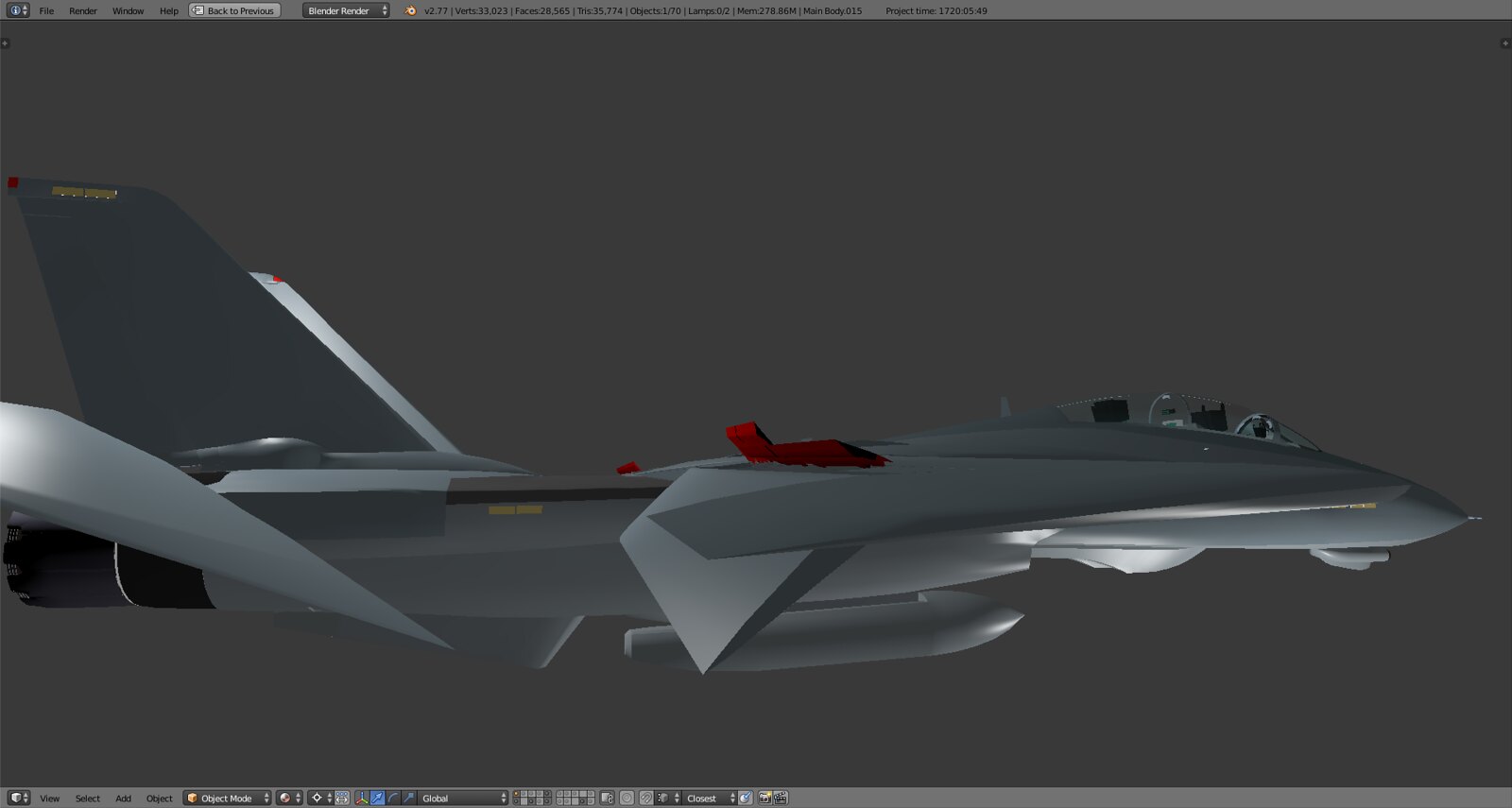
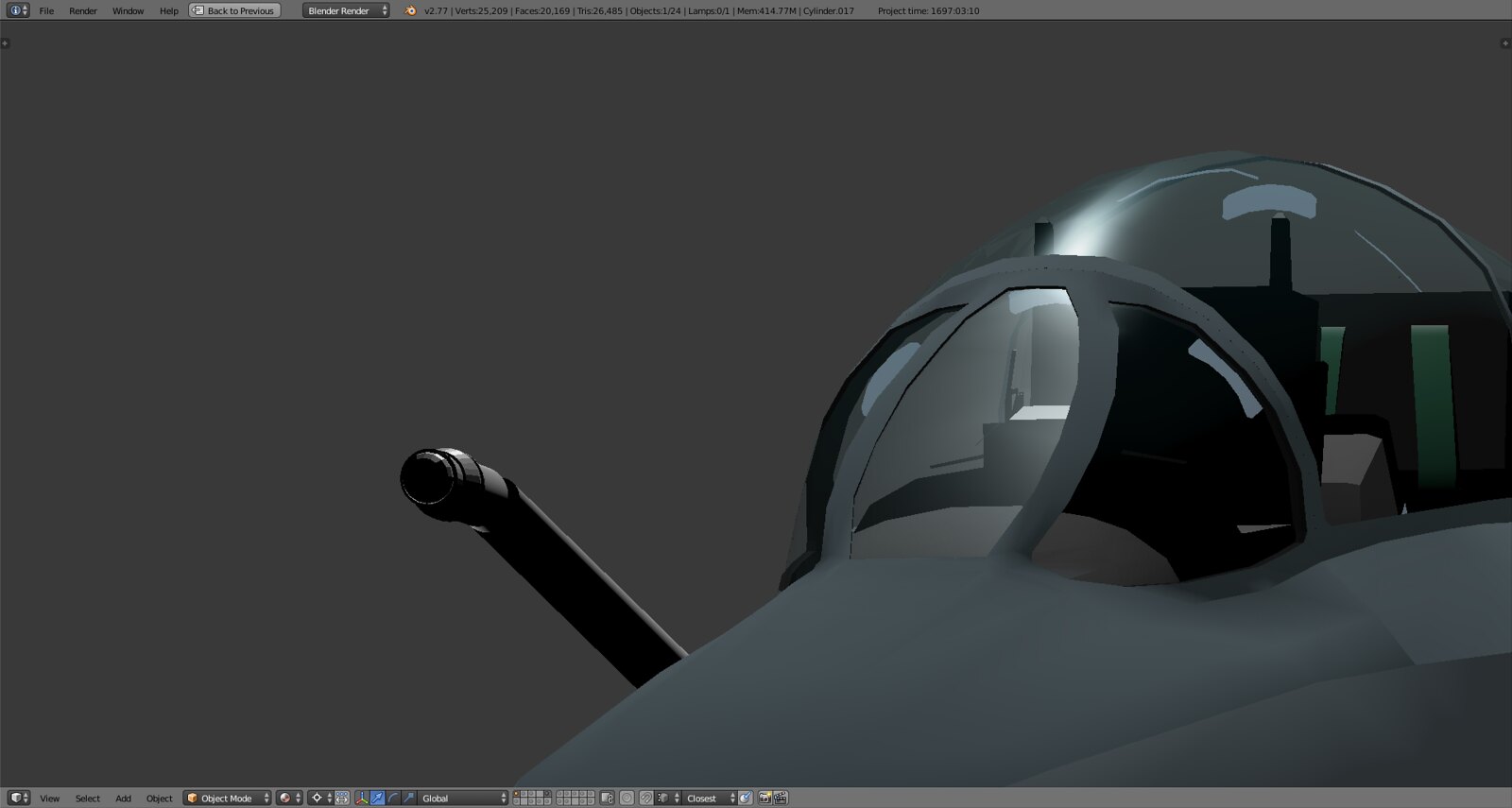
Great progress, Stingray, but I have to make a suggestion. It’s a pain in the ass, but I think you should consider re-working the triangles on the nose into quads for better smoothing. They often look “wrinkled” when shaded and BMS unfortunately will make this worse. It looks like you did a lot of pushing and pulling of vertices to get the shape you wanted, but unfortunately the side effect is the uneven mesh. Just a suggestion, really glad to see your good work on this model!
-
Great progress, Stingray, but I have to make a suggestion. It’s a pain in the ass, but I think you should consider re-working the triangles on the nose into quads for better smoothing. They often look “wrinkled” when shaded and BMS unfortunately will make this worse. It looks like you did a lot of pushing and pulling of vertices to get the shape you wanted, but unfortunately the side effect is the uneven mesh. Just a suggestion, really glad to see your good work on this model!
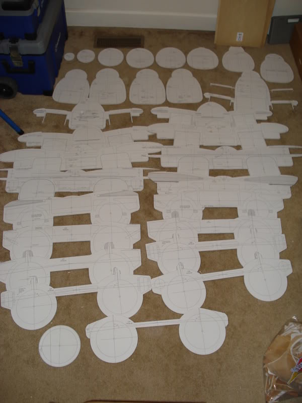
Please do make suggestions, always appreciated. It’s not really a pain, I can do that in 10 minutes as I’ve used a bunch of circles and vertical outlines to build the fuselage as they do in RC modeling so no problem to convert it to quads without losing the general outline. To give you an idea this is what I’m talking about (image courtesy of Thomas W. at rcuniverse):
I noticed the wrinkled nature of the mesh especially along the sides of the fuselage many times and always wondered how exactly I’m gonna get rid of that in the end. So just so I understand correctly you’re basically suggesting to convert it all to quads and align them so that when they’s triangulated (which they inevitably will right?) the triangles fall on one flat rectangular plane and therefore have no extruding edges?!
-
Yes! Exactly. It’s difficult to do manually, so you may end up having to more or less redo it, but you want an even grid of quads. Although everything does eventually get converted to quads, working in triangles makes it very hard to maintain a smooth shape for the rendering engine to shade. It’s especially noticeable with cylindrical shapes like a fuselage. Even the tiniest misalignment of a vertex results in the wrinkled look of misaligned normals! (I’ve learned this by screwing it up, myself.)
Obviously a simple model, but check out the clean grid-like quads of this model. It becomes more difficult to do when you have to consider things like the gunport and formation lights, but it’s still possible.
https://www.turbosquid.com/3d-models/f-14a-tomcat-wolfpack-max/779951I can see in this screenshot, for example, that there are visible seams between your faces around the gunport causing you additional problems. You’ll need to weld those vertices together.
https://www.flickr.com/photos/96028865@N04/32052152034/Again, I would recommend redoing that whole section of the mesh. It’s good that you haven’t started unwrapping/texturing yet, as this will be much harder to stomach once you’ve begun that process. The hardest part will be joining it to the canopy frame without distorting the topology too much. I recommend taking a cross-section near the intakes, and gradually extruding forward, refining the shape (as little changes as needed to match the basic profile of your current nose,) and keeping everything in quads.
-
…Although everything does eventually get converted to quads, working in triangles makes it very hard to maintain a smooth shape for the rendering engine to shade.
You mean: “everything does eventually get converted to triangles” right? BMS doesn’t have any adaptive tessellation, does it?
Stringray: To smooth things out I usually try to select a patch of vertexes then w -> smooth. That might help with the ripples. Are you using the edge-split modifier? If so, are there any edges unintentionally marked sharp?
Also, might be a good idea to keep a super high-res mesh around in case BMS adds normal mapping at a later date (again, they don’t do that yet, do they?). Then the normal map could be baked from the high res mesh, then applied to the lower res one. Though I wonder if panel seams might be the best case for using normal maps in flight sims. Might even be able to get away with just using a monochrome bump map for those.